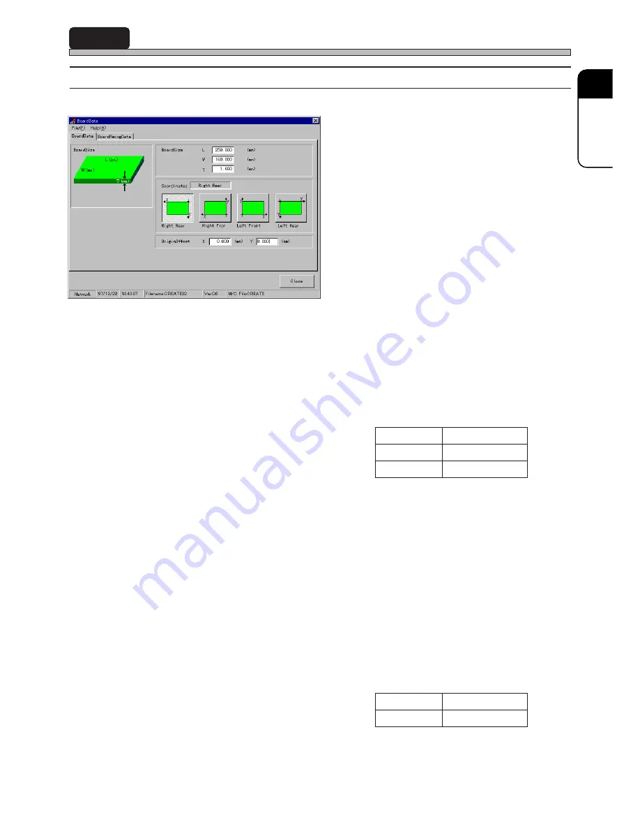
background image

Page 13

22

SP

3

BoardData

3-1

BoardData

1. BoardSize

2. Coordinates

3. OriginOffset

Above contents are as follows.

1. BoardSize

Enter the size of board, L (length), W (width) and T (thickness).
 “L (length)” is a length of the surface parallel to board transport direction. “W (width)” is a length of
the surface vertical to board transport direction. “T (thickness)” is the thickness of board.

2. Coordinates

Choose a board angle as Coordinates.
“Right Rear” is set on SP22. Set the right rear angle as the origin (0, 0) that is a datum for printing
coordinates, etc.

3. OriginOffset

Enter the offset value.
OriginOffset is used to set the origin (0, 0) onto the position other than the board angle as Coordi-
nates. Offset value is the measurement from the angle as Coordinates to the origin.

193C-E-PMA01-A03-01

L (length)

W (width)

T (thickness)

Range to be input

50mm to 330mm

50mm to 250mm

0.5mm to 2.5mm

X (mm)

Y (mm)

Range to be input

0 to board size X

0 to board size Y

193C-EPt-EdBd-001

Содержание SP22P

Страница 1: ...you for purchasing SP22P the screen printer Before placing the machine in service be sure to read the instruction manual for proper usage After that store it carefully and it if necessary Screen Prin...

Страница 2: ......

Страница 3: ...is necessary to get the same number of licenses as them 2 The software cannot be used for several computers on the same network server at the same time For using it for several computers it is necess...

Страница 4: ...r c s e D m e t s y s 5 r e t p a h C X O B P L E H 0 0 1 T P f o n o i s r e v e h t k c e h c o t w o h s e b i r c s e D x i d n e p p A R O T I D E h g i h r e t n i r p n e e r c s f o a t a d n...

Страница 5: ...tion 1 3 2 Chip Data Editing Procedure 1 Click on ChipLibrary ChipLibrary window opens This shows the part to be clicked on This means moving a pointer holding down the left mouse button and laying it...

Страница 6: ...6 MEMO 193C E PMC00 B02 00...

Страница 7: ...imminent danger of death or serious injury This indication refers to a situation which is considered that there is a possibility of death or serious injury This indication refers to a situation which...

Страница 8: ...l out the power plug and wipe off dirt with dry cloth If the machine is not going to be used for a long period turn off the breaker connected with the machine M86E FIRMLY INSERT THE POWER AND OTHER PL...

Страница 9: ...GIVE A SHOCK TO THE ELEC TRICAL EQUIPMENTS There is a risk of an electric shock leak or malfunction of the machine M23E ONLY THE PERSON IN CHARGE MUST CHANGE THE DATA The machine may runaway or malfun...

Страница 10: ...MEMO Page 4 193C E PMA00 B03 00...

Страница 11: ...R SP22 EDITOR SP22 EDITOR SP22 EDITOR is the software to edit the production data of SP22 This Windows application retains the image of current printer editor and is equipped with custom library to ac...

Страница 12: ...PositionData 18 5 2 Editing BoardPositionData 20 6 MaskData 22 6 1 MaskData 22 6 2 Editing MaskData 26 7 Mask Paste Recog 27 7 1 Mask Paste Recog 27 7 2 Editing Mask Paste Recog 29 8 PrintCondition 31...

Страница 13: ...Page 3 22 SP 193C E PMA01 A01 01 12 Print 46 12 1 Print 46 12 2 Executing Print 48 13 BatchTeachData 49 13 1 BatchTeachData 49 INDEX...

Страница 14: ...Page 4 193C E PMA01 A01 01 MEMO...

Страница 15: ...duction data Start Editor to edit the created data PT SP22 Editor Start it from Filer Edit the production data of SP22 Input each detailed data including each recognition data Set function switches in...

Страница 16: ...ting Flow 2 BoardData BoardRecogData Input the data of board to be printed 3 MaskData Input the size of mask and the plate making reference 3Y3C 067E 193C 026E 193C 025E L W T X Y T 1 2 5 6 3 4 7 1 Pr...

Страница 17: ...gee motion and lift motion 7 CleaningData Input the method of mask cleaning 8 PrintCounter Input the solder feed data 9 DataCheck Finally check if all the data are perfect Summary of Data Editing A p...

Страница 18: ...ation area of Filer When starting a new data file see 1 3 Starting New Data File 1 3 Starting New Data File When you start a new data file of SP22 the following screen appears The data chosen from the...

Страница 19: ...windows and its name is displayed in Reference field Six pattern library data are prepared as our standard data beforehand 2 Previous Next The previous or next pattern is displayed by clicking 1 4 SP...

Страница 20: ...nd Some menus contain sub menus 2 Switches for each data editing When you click on a switch Editor main screen closes and the screen for each data editing is displayed E g BoardData 3 Switches for eac...

Страница 21: ...Summary of Data Editing 1 5 Exiting SP22 Editor When you click on Exit on main menu the following screen appears To exit SP22 Editor Choose the method of save then click on OK 193C EPt EdEt 006 193C E...

Страница 22: ...same as that of each data editing screen 2 2 Main Functions This part describes main functions of Editor simply File Drive You can open each data editing screen Print This is used to print each data C...

Страница 23: ...ordinates Choose a board angle as Coordinates Right Rear is set on SP22 Set the right rear angle as the origin 0 0 that is a datum for printing coordinates etc 3 OriginOffset Enter the offset value Or...

Страница 24: ...re input as example as follows 1 Click on BoardData BoardData sheet on BoardData window opens 2 Enter BoardSize Enter the board size L W T 3 Choose a Coordinates Enter OriginOffset if necessary 4 Clic...

Страница 25: ...recognition point a Recognition point coordinates X Y Enter the measurement X Y that is from the origin to board recognition mark E g Right Rear BoardRecogA point X1 Y1 BoardRecogB point X2 Y2 Choose...

Страница 26: ...n BoardRecog in FuncSwitch window is OFF you can not edit 1 Click on BoardRecogData BoardRecogData sheet on BoardData window opens 2 Enter the coordinates of BoardRecogA point 3 Click on SelectREF Set...

Страница 27: ...Color enter the Size and then click on OK SetREF window closes and BoardRecogData sheet opens 5 Input the data of B point by repeating the procedures from 2 to 4 6 Click on Close Main menu is display...

Страница 28: ...port block has risen up to the upper limit and then the set DelayTime has passed board is clamped It is effective for the board whose material is ceramic etc Min After board is clamped at the lower li...

Страница 29: ...pFinishTime considering the lowering speed and lowering stroke PUpFinishTime When the board support starts to lower in order to eject the printed board the timer 0 Depending on board the solder might...

Страница 30: ...ming 3 Set BoardStopperPosition Only when Motion is ON input YDirectPos 4 Set BoardPickUpTimming Usually perform the procedure 6 because the board suction motion is an option 5 Set whether to use Boar...

Страница 31: ...SP BoardPositionData 6 Set UnderGuardStroke Choose Large for the both side mounted board Small for the one side mounted board 7 Click on Close Main menu is displayed again 193C EPt EdBp 006 193C E PM...

Страница 32: ...4 MaskOrigin Above contents are as follows 1 MaskEntryNo When registering mask data input the registration No and name for distinction 2 MaskSize Enter the size of mask Y length X width and T thickne...

Страница 33: ...k frame 250mm 330mm 550mm 160mm 250mm 200mm 150mm 650mm 250mm 330mm 550mm CL 250mm 650mm 160mm CL Sample board pattern position Transport direction 650X550 mask X direction center distribution Positio...

Страница 34: ...the right edge side of X direction mask frame Y direction center distribution Left Center 550X650 mask Position of 110mm from the left edge side of X direction mask frame Y direction center distribut...

Страница 35: ...Left mask 550 X 650 is made as longitudinal frame standard and rear center reference Therefore when you choose the plate making reference as Rear Center the left position is the origin of the mask of...

Страница 36: ...C E PMA01 A03 02 MaskData 6 2 Editing MaskData 1 Click on MaskData 2 Enter the MaskEntryNo and the regis tration name 3 Enter MaskSize 4 Choose a BoardMakeBase 5 Enter the MaskOrigin 6 Click on Close...

Страница 37: ...ted area inspection and clogged mask inspection It is not possible to input 0 time So if you do not use the solder recognition function turn OFF PrintStatusRecog in FuncSwitch window 2 Recognition mod...

Страница 38: ...g Solder is recognized When you perform the printing condition check of machine adjustment the deviation quantity of solder is calculated and the offset data of the printing position check position is...

Страница 39: ...sk Paste Recog Mask Paste Recog window opens 2 Set PasteRecogCount When regarding the check as important Set the higher number of times When regarding the tact time as important Set the lower number o...

Страница 40: ...pair 7 Input the coordinates of recognition point 8 Input the next block data by repeating the procedures from 5 to 7 9 Click on DataShift Board Mask The coordinates of board side are copied to those...

Страница 41: ...e d ChangeLeaveSpeed Above contents are as follows 1 Squeegee a MotionMode Choose 1 round printing motion Single or 2 round printing motion Double b PriorityAfterPrint Set which should move first afte...

Страница 42: ...among the following three modes Const The support block lowers the DWStroke distance with uniform velocity Accel The speed of the support block accelerates slowly from slower speed and eventually it r...

Страница 43: ...g PrintCondition 1 Click on PrintCondition PrintCondition sheet on PrintCondition window opens 2 Set the data about squeegee 3 Set PrintScope 4 Set the Lift data 5 Click on Close Main menu is displaye...

Страница 44: ...ontacting surface of mask 3 Interval Set the board printing quantity that shows the interval of cleaning motion 4 ProcessWaitCleaning Choose whether or not to perform cleaning motion during waiting ti...

Страница 45: ...orward of the sec ond cleaning in 2 round cleaning mode If a wet cleaning is used in 1 round cleaning mode the cleaning performance may be deteriorated depending on the type of solder Recommended cond...

Страница 46: ...g CleaningData 1 Click on CleaningData CleaningData sheet opens 2 Choose the motion mode 3 Set ProcessWaitCleaning and WaitTime 4 Set Speed Form and Suck 5 Click on Close Main menu is displayed again...

Страница 47: ...ining solder is checked in the chosen check method Sensor or Counter and solder is supplied After no solder is checked by the remaining solder check during F R printing solder is supplied automaticall...

Страница 48: ...Page 38 193C E PMA01 A04 01 PrintCondition 8 6 Editing PrintCounter 1 Click on PrintCounter PrintCounter sheet opens 2 Set SetCnt of PasteCount 3 Set CheckSolderOut and SupplyTime...

Страница 49: ...be saved as library Even the operators who are unaccustomed to the machine can create the data by loading the prepared data in a lump Six patterns of data are prepared for each type of solder as our...

Страница 50: ...01 PrintCondition 8 8 Return to LibData 1 Click on Return to LibData Read from Library window opens 2 Choose a PatternLibrary to be loaded 3 Click on OK Make sure the loaded data name is in PatternLib...

Страница 51: ...22 SP 193C E PMA01 A04 01 PrintCondition 8 9 Reflect to LibData 1 Click on Reflect to LibData Write to Library window opens 2 Input PatternLibrary 3 Click on OK The data are registered as a pattern l...

Страница 52: ...te a little And when you change MaskOrigin see page 25 PrintPosition 0 0 0 changes 2 PrintPosOffset It is used when the positioning deviation due to the difference of the squeegee printing direction o...

Страница 53: ...eck 1 Click on DataCheck DataCheck window opens 2A Confirm the Normal result When all the data are normal data editing is completed Click on Close to return to main menu or 2B Confirm the Abnormal res...

Страница 54: ...t s e h T k s a m f o e r u t r e p a g o c e R r e t f A g n i n a e l C c i t a m o t u a g n i r u d n o i t i n g o c e r r e d l o s y b d e t c e t e d s i k s a m d e g g o l c e h t n e h W d...

Страница 55: ...FuncSwitch 11 2 Setting FuncSwitch 1 Click on FuncSwitch FuncSwitch window opens 2 Set the function to be executed on machine at production to ON After setting click on Close to return to main menu 1...

Страница 56: ...Print 12 1 Print It is used to print out the data of chosen item 1 Preview 2 Print Above contents are as follows 1 Preview See the next page 2 Print After setting for printing data are printed on pri...

Страница 57: ...d page of the pages to be printed out is displayed 2 Previous Next The previous or next page from the current page is displayed 3 Reduce Magnify The current page zooms in or out 4 Print After setting...

Страница 58: ...print window opens 2 Check off the item to be printed out 3 Click on Print Perform printing following the setting for printing When checking or editing the printing image click on Preview 4 Click on...

Страница 59: ...becomes the data for solder recognition only Not in use Mask Solder recognition data becomes the data for mask recognition and solder recognition 2 Recog position Set the mask recognition coordinates...

Страница 60: ...Page 50 193C E PMA01 A04 01 MEMO...

Страница 61: ...9 Editing MaskData 26 Editing PrintCondition 33 Editing PrintCounter 38 Editing PrintPosition 42 Executing data check 43 Exiting SP22 editor 11 F Form 34 FuncSwitch 44 I Interval 34 L Left center 24 L...

Страница 62: ...35 SupplySolder 37 Switches for each data editing 10 Switches for each function 10 T TestMode 44 U UnderGuardStroke 19 W WaitForPrint 44 WaitTime 34 Wet cleaning 35 Y YDirectClampTimming 18 193C E PM...

Отзывы: