

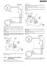

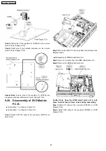


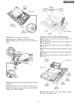


Step 16 Remove 5 screws at the rear panel.
Step 17 Release the catches and remove the fan unit.
Step 18 Release the tab of the rear panel in the direction of
arrow.
Step 19 Detach D-Amp P.C.B. from the bottom chassis and flip
it vertically.
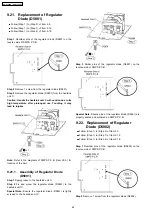
Step 20 Position Main P.C.B. according to the diagram shown.
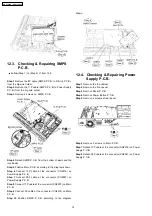
Step 21 Attach original cable with extension cable REXX0651.
(8P cable from H5801 to CN5500).
Caution Note: Ensure the cable is attached properly.
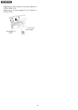
Step 22 Connect 13P cable at the connector (CN2016) on
Power Supply P.C.B.
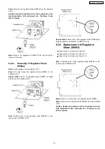
Step 23 Connect 28P cable at the connector (CN6001) on
Power Supply P.C.B.
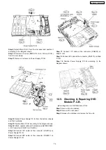
Step 24 Connect 17P cable at the connector (CN2007) on
Main P.C.B.
Step 25 Connect 4P cable at the connector (CN2013) on Main
P.C.B.
Step 26 Connect the 14P cable at the connector (CN2003) on
Main P.C.B.
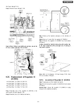
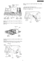
Step 27 Connect the fan unit at the connector (CN5501) on D-
Amp P.C.B.
Step 28 Position D-Amp P.C.B. with insulated material
according to the diagram shown.
73
SA-PT960P / SA-PT960PC
Содержание SA-PT960P
Страница 12: ...12 SA PT960P SA PT960PC ...
Страница 44: ...44 SA PT960P SA PT960PC ...
Страница 46: ...9 2 Main Components and P C B Locations 46 SA PT960P SA PT960PC ...
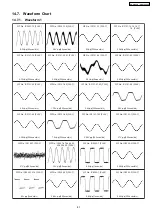
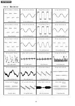
Страница 80: ...14 Voltage and Waveform Chart 14 1 DVD Module P C B 80 SA PT960P SA PT960PC ...
Страница 92: ...SA PT960P SA PT960PC 92 ...
Страница 102: ...102 SA PT960P SA PT960PC ...
Страница 130: ...CN5501 Fig 3 Fan Connector 130 SA PT960P SA PT960PC ...
Страница 132: ...Table 1 132 SA PT960P SA PT960PC ...
Страница 136: ...136 SA PT960P SA PT960PC ...
Страница 141: ...24 Exploded Views 24 1 Cabinet Parts Location SA PT960P SA PT960PC 141 ...
Страница 142: ...24 2 Packaging SA PT960P SA PT960PC 142 ...