


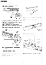
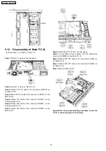


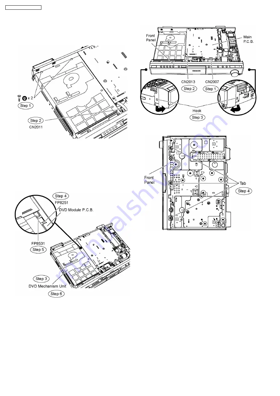
Step 1 Remove 2 screws from mechanism unit.
Step 2 Detach 11P FFC cable at the connector (CN2011) on
Power Supply P.C.B.
Step 3 Move aside mechanism unit and position it according to
the diagram show.
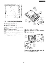
Step 4 Detach 7P FFC cable at the connector (FP8251) on
DVD Module P.C.B.
Step 5 Detach 26P FFC cable at the connector (FP8531) on
DVD Module P.C.B.
Step 6 Remove the mechanism unit.
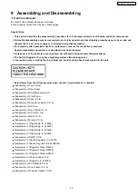
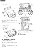
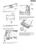
9.6. Disassembly of Front Panel
•
•
•
•
Follow (Step 1) to (Step 3) of Item 9.3.
Step 1 Detach 17P FFC cable at the connector (CN2007) on
Main P.C.B.
Step 2 Detach 4P FFC cable at the connector (CN2013) on
Main P.C.B.
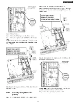
Step 3 Release the hook at each side of the front panel in the
direction of arrow.
Step 4 Release the tabs at the bottom of the front panel.
Caution: Do not exert strong force when releasing the tabs.
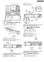
Step 5 Detach the front panel slightly forward in the direction of
arrows.
Step 6 Detach 14P cable at the connector (CN6003) on Power
Supply P.C.B.
Step 7 Remove the front panel.
48
SA-PT960P / SA-PT960PC
Содержание SA-PT960P
Страница 12: ...12 SA PT960P SA PT960PC ...
Страница 44: ...44 SA PT960P SA PT960PC ...
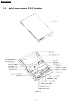
Страница 46: ...9 2 Main Components and P C B Locations 46 SA PT960P SA PT960PC ...
Страница 80: ...14 Voltage and Waveform Chart 14 1 DVD Module P C B 80 SA PT960P SA PT960PC ...
Страница 92: ...SA PT960P SA PT960PC 92 ...
Страница 102: ...102 SA PT960P SA PT960PC ...
Страница 130: ...CN5501 Fig 3 Fan Connector 130 SA PT960P SA PT960PC ...
Страница 132: ...Table 1 132 SA PT960P SA PT960PC ...
Страница 136: ...136 SA PT960P SA PT960PC ...
Страница 141: ...24 Exploded Views 24 1 Cabinet Parts Location SA PT960P SA PT960PC 141 ...
Страница 142: ...24 2 Packaging SA PT960P SA PT960PC 142 ...