

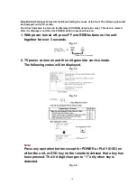
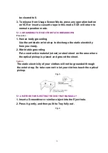


1. Turn off TV set.
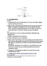
2. Connect the circuit below between TP554 and TP555 on the TV
Main C.B.A.
Figure 2
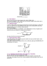
3. Turn on SW1 and then turn on the set. Confirm that the picture is
on the screen properly.
4. Confirm that the picture goes out of horizontal sync while getting
down by varying VR.
5. If this does not occur, it means that X-ray protect circuit is not
operating. Further confirmation and repair is required.
2.2. REPAIR PROCEDURES OF HORIZONTAL OSCILLATOR
DISABLE CIRCUIT
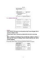
1. Connect a DC voltmeter between capacitor C513 (+) on the Main
circuit board and chassis ground.
2. If approxi18.5 V (For model with Round 20 inch CRT), +
21.5 V (For model with Flat 20 inch CRT), +22.0 V (For model with
Round 27 inch CRT), +20.0 V (For model with Flat 27 inch CRT) is
not presentat that point when 120 V AC is applied, find the cause.
Check R508, R503, R5504, R5505, D503, C513, C5507 and J5501.
3. Carefully check above specified parts and related circuits and
parts. When the circuit is repaired, try the horizontal oscillator
disable circuit test again.
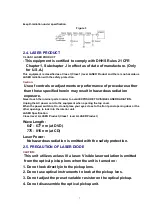
2.3. CIRCUIT EXPLANATION
2.3.1. HORIZONTAL OSCILLATOR DISABLE CIRCUIT
The positive DC voltage, supplied from the D503 cathode for monitoring high voltage, is applied
to the IC5301 Pin11 through R508, R503 and R5504. Under normal conditions, the voltage at
IC5301 Pin 11 is less than approx. 6 V. If the high voltageat Flyback Transformer Pin 5 exceeds
the specified voltage, the positive DC voltage which is supplied from the D503 cathode also
increases. The increased voltage is applied to IC5301 Pin11 through R508, R503 and R5504. Due
to the increased voltageat IC5301 Pin11, the horizontal oscillator frequency increases, the picture
goes out of horizontal sync, the beam current decreases and the picture become dark in order to
6
Содержание PVDF204 - DVD/VCR/TV COM
Страница 11: ...Fig 1 5 11 ...
Страница 12: ...Fig 1 6 12 ...
Страница 25: ...Fig D2 25 ...
Страница 26: ...Fig D3 26 ...
Страница 27: ...Fig D4 27 ...
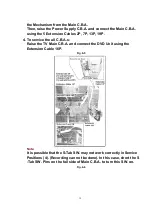
Страница 28: ...6 1 1 1 Notes in chart 1 Removal of VCR DVD Ass y Fig D5 28 ...
Страница 48: ...7 4 TEST POINTS AND CONTROL LOCATION 48 ...
Страница 51: ...11 2 DVD SECTION 51 ...
Страница 52: ...11 3 CHASSIS FRAME SECTION 1 Model A B C D E F 52 ...
Страница 53: ...11 4 CHASSIS FRAME SECTION 2 53 ...
Страница 54: ...11 5 CHASSIS FRAME SECTION 3 54 ...
Страница 55: ...11 6 PACKING PARTS AND ACCESORIES SECTION 55 ...
Страница 71: ...R6006 ERJ6GEYJ102V MGF CHIP 1 10W 1K 71 ...