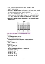
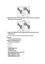
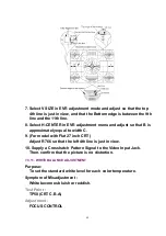

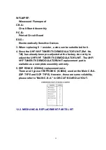
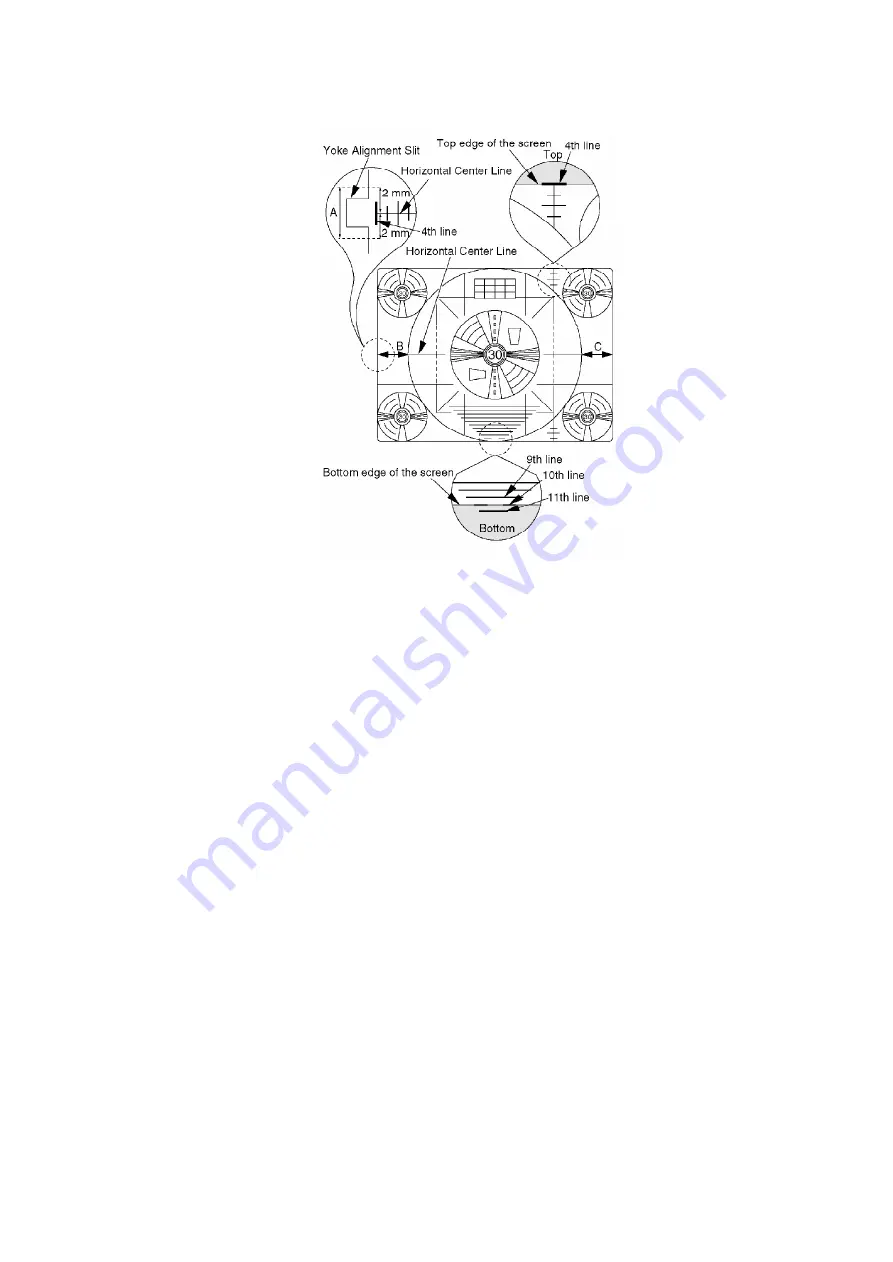
7. Select V SIZE in EVR adjustment mode and adjust so that the top
4th line is just in view, and that the Bottom edge is between the 9th
line and the 11th line.
8. Select H-CENTER in EVR adjustment menu and adjust so that B is
approximately equal to width C.
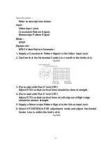
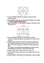
9. (For model with Flat 27 inch CRT)
Adjust R766 so that the left 4th line is just in view.
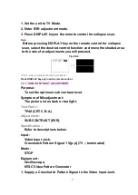
10. Supply a Crosshatch Pattern Signal to the Video Input Jack.
Then, confirm that the picture is no distortion.
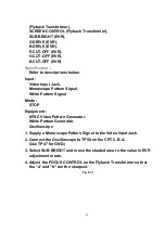
7.3.11. WHITE BALANCE ADJUSTMENT
Purpose:
To set the standard white level for each color temperature.
Symptom of Misadjustment :
White becomes bluish or reddish.
Test Point :
TP50 (CRT C.B.A)
Adjustment :
FOCUS CONTROL
44
Содержание PVDF204 - DVD/VCR/TV COM
Страница 11: ...Fig 1 5 11 ...
Страница 12: ...Fig 1 6 12 ...
Страница 25: ...Fig D2 25 ...
Страница 26: ...Fig D3 26 ...
Страница 27: ...Fig D4 27 ...
Страница 28: ...6 1 1 1 Notes in chart 1 Removal of VCR DVD Ass y Fig D5 28 ...
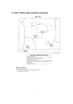
Страница 48: ...7 4 TEST POINTS AND CONTROL LOCATION 48 ...
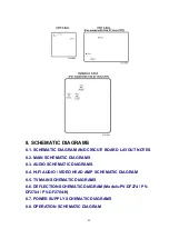
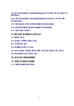
Страница 51: ...11 2 DVD SECTION 51 ...
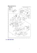
Страница 52: ...11 3 CHASSIS FRAME SECTION 1 Model A B C D E F 52 ...
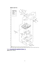
Страница 53: ...11 4 CHASSIS FRAME SECTION 2 53 ...
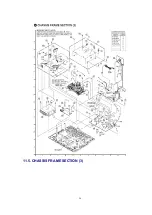
Страница 54: ...11 5 CHASSIS FRAME SECTION 3 54 ...
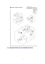
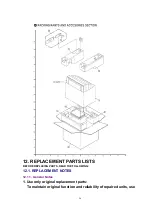
Страница 55: ...11 6 PACKING PARTS AND ACCESORIES SECTION 55 ...
Страница 71: ...R6006 ERJ6GEYJ102V MGF CHIP 1 10W 1K 71 ...