
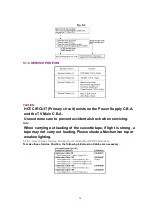


5.1.7. HOT CIRCUIT
Primary circuit exists on the Power Supply C.B.A. and the TV Main C.B.A.
This circuit is identified as " HOT " on the C.B.A. and in the Service Manual. Use extreme care to
prevent accidental shock when servicing.
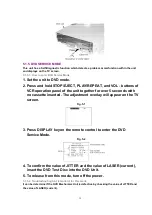
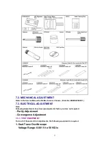
5.1.8. SERVICE MODE
In order to inhibit detection of the Supply & Takeup Photo Transistors, Reel Sensor, and Cylinder
Lock can be inhibited. In this mode, Mechanism movement can be confirmed. When removing
Cassette Up Ass'y, it can be confirmed withouta cassette.
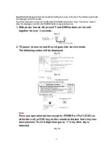
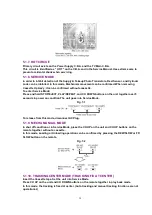
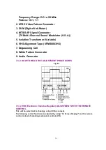
To enter Service Mode:
Press and hold STOP/EJECT, PLAY/REPEAT, and CH DOWN buttons on the unit together over 5
seconds in power on condition.The unit goes into Service Mode.
Fig. 7-1
To release from this mode, disconnect AC Plug.
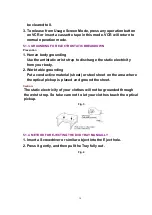
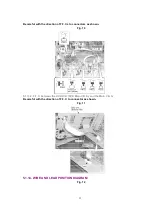
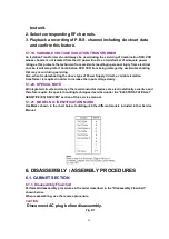
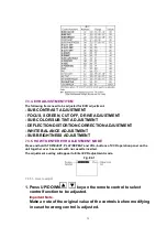
5.1.9. MECHA MANUAL MODE
In shut off condition or in Service Mode, press the CH UP on the unit and CH UP buttons on the
remote together without a cassette.
In this mode, Loading or Unloading operation can be confirmed by pressing the REW/SLOW or FF/
SLOW button on the remote.
Fig. 7-2
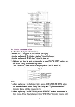
5.1.10. TRACKING CENTER MODE (TRACKING FIX AT CENTER)
Insert the Cassette tape. Set the unit into Service Mode.
Press CH UP on the unit and CH DOWN buttons on the remote together in play back mode.
In this mode, the tracking is fixed at center. (Auto tracking and manual tracking functions are not
operational.)
20
Содержание PVDF204 - DVD/VCR/TV COM
Страница 11: ...Fig 1 5 11 ...
Страница 12: ...Fig 1 6 12 ...
Страница 25: ...Fig D2 25 ...
Страница 26: ...Fig D3 26 ...
Страница 27: ...Fig D4 27 ...
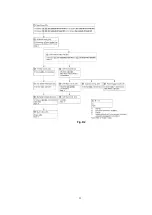
Страница 28: ...6 1 1 1 Notes in chart 1 Removal of VCR DVD Ass y Fig D5 28 ...
Страница 48: ...7 4 TEST POINTS AND CONTROL LOCATION 48 ...
Страница 51: ...11 2 DVD SECTION 51 ...
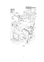
Страница 52: ...11 3 CHASSIS FRAME SECTION 1 Model A B C D E F 52 ...
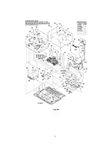
Страница 53: ...11 4 CHASSIS FRAME SECTION 2 53 ...
Страница 54: ...11 5 CHASSIS FRAME SECTION 3 54 ...
Страница 55: ...11 6 PACKING PARTS AND ACCESORIES SECTION 55 ...
Страница 71: ...R6006 ERJ6GEYJ102V MGF CHIP 1 10W 1K 71 ...