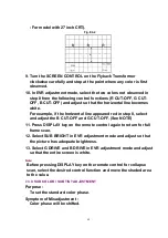

5. Turn the SCREEN CONTROL on Flyback Transformer fully
counterclockwise.
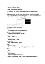
6. Press DISPLAY key on the remote control for collapse scan. (Refer
to "
HOW TO ENTER SERVICE MODE
.")
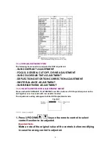
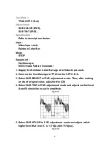
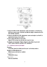
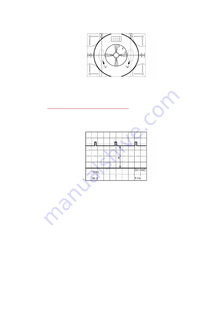
7. Adjust SUB BRIGHT in EVR adjustment mode so that the level A is
175 VDC±5 VDC.
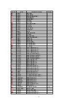
Fig. E7-2
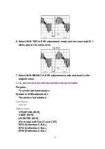
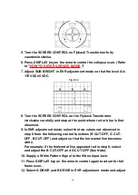
8. Turn the SCREEN CONTROL on the Flyback Transformer
clockwise carefully and stop at the point where red or blue is first
observed.
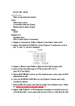
9. In EVR adjustment mode, select the two colors not observed in
step 8 from the following control functions (R CUT-OFF, G CUT-
OFF, B CUT-OFF) and adjust so that the horizontal line becomes
white.
For example, if the horizontal line appeared red in step 8, select
and adjust the B CUT-OFF and G CUT-OFF (See Note).
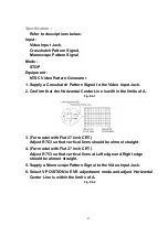
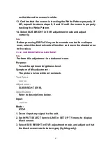
10. Supply a White Pattern Signal to the Video Input Jack.
11. Press DISPLAY key on the remote control again to return for full
frame scan.
12. Select G DRIVE and B DRIVE in EVR adjustment mode and adjust
46
Содержание PVDF204 - DVD/VCR/TV COM
Страница 11: ...Fig 1 5 11 ...
Страница 12: ...Fig 1 6 12 ...
Страница 25: ...Fig D2 25 ...
Страница 26: ...Fig D3 26 ...
Страница 27: ...Fig D4 27 ...
Страница 28: ...6 1 1 1 Notes in chart 1 Removal of VCR DVD Ass y Fig D5 28 ...
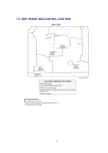
Страница 48: ...7 4 TEST POINTS AND CONTROL LOCATION 48 ...
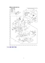
Страница 51: ...11 2 DVD SECTION 51 ...
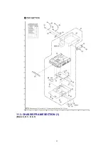
Страница 52: ...11 3 CHASSIS FRAME SECTION 1 Model A B C D E F 52 ...
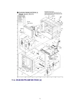
Страница 53: ...11 4 CHASSIS FRAME SECTION 2 53 ...
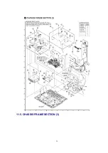
Страница 54: ...11 5 CHASSIS FRAME SECTION 3 54 ...
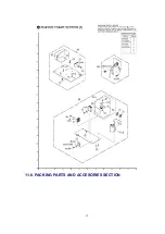
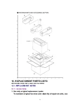
Страница 55: ...11 6 PACKING PARTS AND ACCESORIES SECTION 55 ...
Страница 71: ...R6006 ERJ6GEYJ102V MGF CHIP 1 10W 1K 71 ...