background image

33


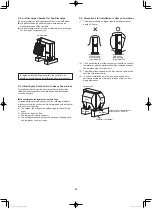
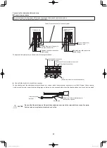
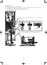
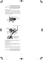
Wiring procedure

Follow the wiring procedure below for terminal connection.
(1)  Set the wiring and cables for the power and signal lines to the outdoor unit together, and secure each wire and cable with the tie.
(2)  Secure and clamp the power and signal lines with the tie, set up close to the valve.
(3)  Set up the wiring and cable for the outdoor unit piping and secure with a tie.

1

   Secure and clamp the wiring and cable with the tie (field supply) for the power and signal lines 

to the outdoor unit.

2

   Secure and clamp the wiring and cable together with power and signal lines using the tie set 

up close to the valve.

3

   Secure and clamp all wiring and cable together with the indoor/outdoor piping using the tie 

(field supply).

Correct

Incorrect

Do not remove the Mylar Tape.

00_291827_2WAY_Eng.indb   33

2017/7/5   13:41:33

Содержание mini VRF U-4LE2R5

Страница 1: ...MP1E5 S 36MP1E5 S 45MP1E5 S 56MP1E5 R1 Concealed Floor Standing S 22MR1E5 S 28MR1E5 S 36MR1E5 S 45MR1E5 S 56MR1E5 Z1 Slim Type Ducted S 22MZ1H4A S 28MZ1H4A S 36MZ1H4A S 45MZ1H4A S 56MZ1H4A S 60MZ1H4A...

Страница 2: ...s service outlet or your certified dealer for additional instructions In Case of Improper Installation The manufacturer shall in no way be responsible for improper installation or maintenance service...

Страница 3: ...er to off grid generator power or vice versa to provide power for the air conditioner be sure to follow the guidelines below Otherwise the air conditioner may malfunction due to damage to the PCBs or...

Страница 4: ...door and outdoor units by users Engage authorized dealer or specialist for cleaning In case of malfunction of this appliance do not repair by yourself Contact to the sales dealer or service dealer for...

Страница 5: ...ensity should rise excessively Suffocation from leakage of refrigerant is almost non existent With the recent increase in the number of high density buildings however the installation of multi air con...

Страница 6: ...e recharging the refrigerant in gas form can lower performance and cause defects in the unit 2 2 Since refrigerant composition changes and performance decreases when gas leaks collect the remaining re...

Страница 7: ...nance of this unit 1 Avoid installing the unit at a place where the unit is exposed to sea spray as much as possible 2 Give special consideration to the layout so the salt particles adhering to the ou...

Страница 8: ...ions for Installation in Heavy Snow Areas 2 5 Dimensions of Air Discharge Chamber 2 6 Dimensions of Air Discharge Chamber for Top Discharge 2 7 Dimensions of Snow Proof Vents 3 HOW TO INSTALL THE OUTD...

Страница 9: ...page 23 2 Operating Instructions 1 Installation Instructions 1 1 3 Type of Copper Tube and Insulation Material If you wish to purchase these materials separately from a local source you will need 1 D...

Страница 10: ...r unit 50 When outdoor unit is installed lower than indoor unit 40 H2 Max difference between indoor units 15 Allowable length of joint tubing L3 T joint tubing field supply Max tubing length between t...

Страница 11: ...kW 7 1 2 5 HP Over kW 7 1 2 5 HP Tubing size Gas tube 12 7 15 88 Liquid tube 9 52 9 52 Note In case the total capacity of indoor units connected after distribution exceeds the capacity of the outdoor...

Страница 12: ...ulated below Total tubing length 50 m No additional charge will be necessary Total tubing length 50 m Required amount of additional refrigerant charge Amount of additional refrigerant charge per meter...

Страница 13: ...is charged in the field For the refrigerant charge amount at shipment refer to the unit s nameplate Minimum indoor volume floor area as against the amount of refrigerant is roughly as given in the fol...

Страница 14: ...90 15 30 Straight tubing length over 200mm Branch tubing angle Horizontal Straight tubing length over 200mm or 0 30 Branch tubing angle Horizontal Vertical Upward Vertical Vertical Vertical Vertical D...

Страница 15: ...ze with thermal insulation 1 CZ P160BK2 Use Total capacity of indoor units after distribution joint is 22 4 kW or less Example 110 97 110 97 72 72 B A D B B C C C D E A C D E C Table 12 Size of connec...

Страница 16: ...N 1 R410A additional charging absolutely must be done through liquid charging 2 The R410A refrigerant cylinder has a gray base color and the top part is pink 3 The R410A refrigerant cylinder includes...

Страница 17: ...e of a room using an indoor unit of minimum capacity For instance when an indoor unit is used in a room floor area 8 00 m2 ceiling height 2 7 m room volume 21 6 m3 the minimum room volume should be 22...

Страница 18: ...s in the descriptions 1 to 10 For other installation examples refer to the Technical Data It is possible to reduce the space between the air discharge outlet and an obstacle by installing the field su...

Страница 19: ...space The outdoor units require necessary space to unscrew on the rear side for maintenance and if a sufficient maintenance space is provided on the rear side 400 mm the space of over 150 mm is enough...

Страница 20: ...chamber in the field when it is difficult to keep a sufficient space between the air discharge outlet and an obstacle the air discharge outlet is facing a sidewalk and discharged hot air may annoy pas...

Страница 21: ...r upward greater than that of the section 2 5 Dimensions of Air Discharge Chamber use this type of chamber as shown in the following illustration 486 627 173 3 195 7 370 116 996 980 612 43 5 324 5 Air...

Страница 22: ...Single unit installation 2 Obstacles on both sides For other installation examples refer to the Technical Data Note The amount of space is required for removing the screw on the rear of the unit If in...

Страница 23: ...g The tubing and wiring can be extended out in 4 directions front rear right and down The service valves are housed inside the unit To access them remove the inspection panel To remove the inspection...

Страница 24: ...facturer will accept no responsibility for any damage or misoperation that occurs as a result of such unauthorized changes 7 Regulations on wire diameters differ from locality to locality For field wi...

Страница 25: ...5 A Indoor unit Type B Power supply Time delay fuse or circuit capacity D1 L1 U2 Y2 K1 K2 T2 F2 M1 P1 R1 E1 Z1 Refer to the Installation Instructions of the indoor unit Control wiring C Inter unit bet...

Страница 26: ...efore turning the power on 4 Regarding the R C address setting it can be executed by remote controller automatically See the section 7 4 Auto Address Setting 2P terminal board Power supply L N 2P term...

Страница 27: ...trol wiring the number of branch points should be 16 or fewer Outdoor unit Central Controller Outdoor unit Indoor unit Indoor unit Indoor unit Indoor unit Indoor unit Indoor unit Indoor unit Indoor un...

Страница 28: ...the wire end with cutting pliers then strip the insulation to expose the stranded wiring about 10 mm and tightly twist the wire ends Stranded wire Ring pressure terminal Strip 10 mm 2 Using a Phillips...

Страница 29: ...cm 1 kgf cm ATTENTION Comply with the torque values If tightening over torque values the screw will be damaged ATTENTION Apply an adjustable wrench to the valve vertically not to damage the P C board...

Страница 30: ...spaces and adjust it so the shield part does not touch any live parts CAUTION Be sure that the shield part of the shielded cable does not touch the terminal block or any live parts Failure to do so m...

Страница 31: ...l block Terminal block DRED Demand controller Relay contact point No voltage relay Current input is DC 24 V 10 mA When connecting the demand controller input It is possible to choose the desired deman...

Страница 32: ...g 2 wire to the terminal points 1 and 2 at the lower right side of the terminal block The shield part of the shielded cable is connected with SG under the terminal block Secure the wiring with the cor...

Страница 33: ...the wiring and cable for the outdoor unit piping and secure with a tie 1 Secure and clamp the wiring and cable with the tie field supply for the power and signal lines to the outdoor unit 2 Secure and...

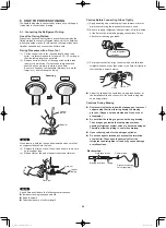
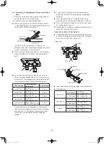
Страница 34: ...Connecting Tubes Tightly 1 Apply a sealing cap or water proof tape to prevent dust or water from entering the tubes before they are used 2 Be sure to apply refrigerant lubricant ether oil to the insi...

Страница 35: ...100 120 N m 1000 1200 kgf cm 1 2 mm Because the pressure is approximately 1 6 times higher than conventional refrigerant pressure the use of ordinary flare nuts type 1 or thin walled tubes may result...

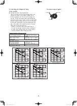
Страница 36: ...as tubing 120 C or above Other tubing 80 C or above Calculating condition Thermal conductivity of insulation material 0 043 W m K Average temperature 23 C Refrigerant temperature 2 C Two tubes arrange...

Страница 37: ...vinyl clamps Refrigerant tubing and insulator Drain pipe and insulator Drain insulator and clamp Packing clamp The procedure used for installing the insulator for both gas and liquid tubes is the same...

Страница 38: ...ap half of each previous tape turn 3 Clamp the tubing bundle to the wall using 1 clamp approx each meter Drain hose Communication line Clamp Insulated tubes NOTE Do not wind the armoring tape too tigh...

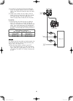
Страница 39: ...his stage Leak test 1 With the service valves on the outdoor unit closed remove the 1 4 in flare nut and its bonnet on the gas tube service valve Save for reuse 2 Attach a manifold valve with pressure...

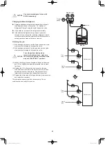
Страница 40: ...tion time for evacuation varies with the tubing length and capacity of the pump The following table shows the amount of time for evacuation Required time for evacuation when 30 gal min vacuum pump is...

Страница 41: ...unter clockwise to fully open the valve CAUTION To avoid gas from leaking when removing the charge hose make sure the stem of the gas tube is turned all the way out BACK SEAT position 3 Loosen the cha...

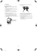
Страница 42: ...hould be warm to the touch and the crankcase heater around the feet of the compressor should be hot to the touch ON Power must be turned ON at least 5 hours before attempting test run Power mains swit...

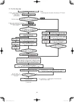
Страница 43: ...ernately Approx 2 3 minutes Set the number of indoor units CASE 1 CASE 2 Are LEDs 1 and 2 on outdoor unit P C board OFF Connect link wires to original place Are LEDs 1 and 2 on outdoor unit P C board...

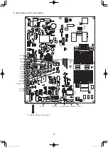
Страница 44: ...Unit P C Board Setting U LED 2 LED 1 SW 2 SW 1 SW 4 SW 3 DEF A ADD CHK AP STOP RUN MODE CN SILENT CN ROM CN OC CN EMG For detailed drawing see the page 46 CN RC CN TERMINAL 00_291827_2WAY_Eng indb 44...

Страница 45: ...ting more than 10 the communication cannot be made between the outdoor and indoor units Examples of refrigerant circuit R C address settings required when link wiring is used SW1 SW2 System address No...

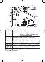
Страница 46: ...o if short circuit is cancelled test run mode is cancelled RC plug 3P BLU Connects to outdoor unit maintenance remote controller and content of alarm message will be checked RUN pin 2P BLK When short...

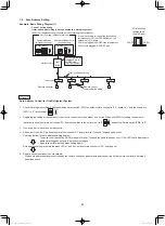
Страница 47: ...setting is completed when LEDs 1 and 2 on outdoor main unit control P C board go out 5 Remote control operation is now available When auto address setting is controlled by the remote controller perfor...

Страница 48: ...its 9 units setting Unit 1 Main Set the terminating resistance pin to SHORT side CN TERMINAL Remote control communication wiring Outdoor unit system 1 Inter unit control wiring Inter unit control wiri...

Страница 49: ...tdoor main unit control P C board in 1 refrigerant system is set to 1 and the Dip switch SW1 is set to 0 at shipment 2 1 ON ON OFF 2 Regarding the number of indoor units connected to the outdoor unit...

Страница 50: ...etting is completed 5 Repeat the same steps to perform auto address setting for each successive system Auto Address Setting from the High spec Wired Remote Controller CZ RTC5A 4 Select the O D unit no...

Страница 51: ...dress indoor EEPROM item code 13 is set more than 13 indoor units In this case be sure to set the indoor unit address less than 12 Under auto address setting Alternately Auto address setting completed...

Страница 52: ...simple settings mode 2 The address is displayed for the indoor unit that is connected to the remote controller Only the address of the indoor unit that is connected to the remote controller can be che...

Страница 53: ...remote controller 1 Press the remote controller button for 4 seconds or longer Then press the button appears on the LCD display while the test run is in progress The temperature cannot be adjusted wh...

Страница 54: ...Self Diagnosis Function Table Cause and countermeasure against the symptom of auto address failure Symptom Cause and countermeasure When turning ON power to the outdoor main unit LEDs 1 and 2 illumin...

Страница 55: ...ess setting may not occasionally be made although under setting is displayed 3 Although the alarm E15 and E16 are displayed addresses will be installed in the recognized indoor units The installed add...

Страница 56: ...discharge temperature sensor is disconnected shorted or misplaced DISCH1 H06 Low pressure sensor value is too low H31 Compressor 1 HIC has failure HIC is overcurrent or overheat VDC is undervoltage or...

Страница 57: ...has failure BL P09 Connection to the panel of indoor unit is not good P01 Activation of protective device for Indoor unit Thermal protector for Indoor unit fan motor is activated P10 Float switch of...

Страница 58: ...alid OPEN side It is prohibited making more than 3 locations of terminating resistance valid Since the use of linking the sub outdoor units of VRF systems is not connected to the inter unit control wi...

Страница 59: ...59 NOTE 00_291827_2WAY_Eng indb 59 2017 7 5 13 41 42...

Страница 60: ...ACXF60 16410 DC0517 20717 Printed in Malaysia 00_291827_2WAY_Eng indb 2 2017 7 5 13 41 42...

Отзывы: