S-2
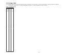
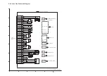
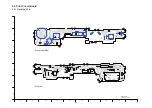
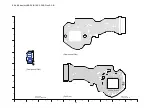
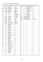
S2. Voltage Chart
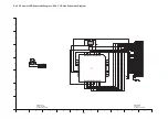
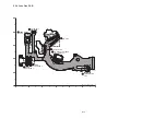
S2.1. Flash Top P.C.B.
Note) Indicated voltage values are the standard values for the unit measured by the DC electronic circuit tester (high-impedance) with the chassis taken as standard.
Therefore, there may exist some errors in the voltage values, depending on the internal impedance of the DC circuit tester.
REF No.
PIN No.
POWER ON
IC8001
1
3
IC8001
2
0
IC8001
3
0
IC8001
4
0
IC8001
5
4.8
Содержание Lumix DMC-FX33E
Страница 12: ...12 4 Specifications ...
Страница 13: ...13 5 Location of Controls and Components ...
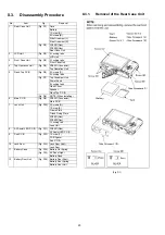
Страница 19: ...19 8 Disassembly and Assembly Instructions 8 1 Disassembly Flow Chart 8 2 PCB Location ...
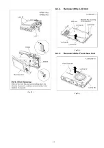
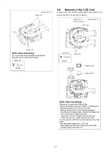
Страница 21: ...21 Fig D2 8 3 2 Removal of the LCD Unit Fig D3 8 3 3 Removal of the Front Case Unit Fig D4 ...
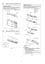
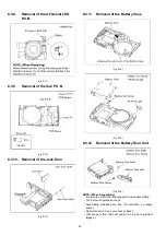
Страница 22: ...22 8 3 4 Removal of the Top Operation Unit Fig D5 8 3 5 Removal of the Flash Top P C B Fig D6 Fig D7 ...
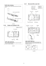
Страница 23: ...23 Fig D8 8 3 6 Removal of the Main P C B Fig D9 8 3 7 Removal of the Lens Unit Fig D10 ...
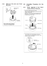
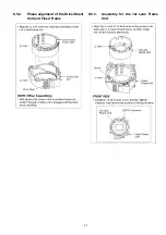
Страница 27: ...27 8 5 2 Phase alignment of the Drive Direct Unit and Fixed Frame 8 5 3 Assembly for the 1st Lens Frame Unit ...
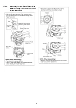
Страница 28: ...28 8 5 4 Assembly for the Zoom Motor Unit Master Frange Unit and 2nd Lens Frame Move Unit ...
Страница 52: ...S7 3 Packing Parts and Accessories Section 2 S 20 308 312 315 314 313 301 303 304 311 310 307 309 306 305 316 ...

