10
KX-NS500AG
4.2.2.
Main Unit Mother Board
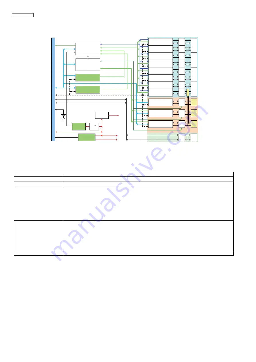
Fig.3 shows detail block diagram of Mother Board, and each function of Base is described in Table.5.
Table.5 Main Unit Mother Board Function Description
4.2.3.
SLIC/CODEC (SLC) Block
Refer to Service Manual of KX-NS5173/KX-NS5174.
4.2.4.
DSP (LCOT) Block
Refer to Service Manual of KX-NS5180.
4.2.5.
DPT I/F Block
Refer to Service Manual of KX-NS5170/KX-NS5171/KX-NS5172.
Device/Function Block
Description
PLD1(EXT_PLD)
PLD1 controls and monitors SLIC/CODEC LSI of each analog line port.
PLD2(CO_PLD)
PLD2 controls the trunk controller DSP which is used in each analog trunk port.
SLIC/CODEC
SLIC/CODEC is exclusive LSI which is used for analog line interface.
1) Line interface power supply
2) Dial pulse detection
3) DTMF receiver / Caller ID generation
4) Bell signal generation
5) Hooking detection / Ringtrip detection
6) 2W/4W conversion
7) CODEC function
DSP(CO)
DSP(CO) is exclusive LSI which is used analog trunk port.
1) Dial pulse generation
2) DTMF signal generation / Caller ID detection
3) Bell signal detection
4) CPC signal detection
5) 2W/4W conversion
6) CODEC function
DPT I/F
DPT I/F is Digital Line Interface.
6
Trun
k
option
Connector
Extension option
Connector
80
P
IN
C
O
N
NE
C
T
O
R
(C
PU
In
te
r
fa
ce)
R
J
45
MOH
P
A
G
R
J
45
R
J
45
POWER I/F
Connector
Exp
a
nsi
on
bu
s
S
LIC/CODEC bus (
S
PI)
TDM Hi
g
h
wa
y bus
A
FE
D
S
P
(
2
ch)
A
FE
A
FE
S
LIC/CODEC(
2
ch)
A
FE
A
FE
A
FE
A
FE
A
FE
A
FE
A
FE
S
LIC/CODEC(
2
ch)
S
LIC/CODEC(
2
ch)
S
LIC/CODEC(
2
ch)
S
LIC/CODEC(
2
ch)
S
LIC/CODEC(
2
ch)
S
LIC/CODEC(
2
ch)
S
LIC/CODEC(
2
ch)
DPT
I/F
(
2
ch)
D
S
P
(
2
ch)
A
C
A
LM, DC
A
LM
+40
V
, GND
+15
V
, GND
Di
a
l Pulse, CPC DET
Di
a
l Pulse, CPC DET
R
J
45
R
J
45
R
J
45
IIO bus
PLD1
( E
X
T_PLD)
D
S
P
(
2
ch)
A
FE
Di
a
l Pulse, CPC DET
DPT- I/F
F
A
N I/F
Connector
V
B
A
T
+15
V
, GND
PLD
2
(CO_PLD)
INT(
2
)
DC/DC
+3.3
V
, GND
15
1
2V
INT_
S
LIC
INT_D
S
P
INT
INT_E
X
T
INT_CO
F
A
N_
A
LM
R
J
45
MOH
P
A
G
R
J
45
MOH
P
A
G
CO1-CO
2
CO
2
-CO3
CO4-CO5
Re
l
a
y
R
J
45
S
LT
2
S
LT1
Fi
g
.3 M
a
in Unit Mother Bo
a
rd Bloc
k
Di
ag
r
am
Содержание KX-NS500AG
Страница 21: ...21 KX NS500AG 5 Location of Controls and Components 5 1 Name and Locations ...
Страница 24: ...24 KX NS500AG 9 1 1 Startup ...
Страница 25: ...25 KX NS500AG ...
Страница 26: ...26 KX NS500AG ...
Страница 27: ...27 KX NS500AG ...
Страница 28: ...28 KX NS500AG 9 1 2 Battery Alarm ...
Страница 29: ...29 KX NS500AG 9 1 3 Using Voice Mail ...
Страница 30: ...30 KX NS500AG Using Voice Mail continued ...
Страница 32: ...32 KX NS500AG 9 2 Power Supply 9 2 1 No Voltage is Output at All 1 Main converter output voltage error C102 ...
Страница 33: ...33 KX NS500AG 9 2 2 No voltage is Output at All 2 Output voltage of Main Converter is Normal C101 C102 ...
Страница 34: ...34 KX NS500AG 9 2 3 41V are Not Output Only 15V is output ...
Страница 35: ...35 KX NS500AG 9 2 4 Battery Backup Function Does Not Operate PSU can Not Charge Batteries ...
Страница 43: ...43 KX NS500AG 11 3 3 Power Supply Board ...
Страница 59: ...59 KX NS500AG 12 2 Memo ...
Страница 73: ...73 KX NS500AG 12 5 Memo ...
Страница 131: ...131 KX NS500AG 16 Appendix ...


