7
KX-FT932BR-B
2 Warning
2.1.
About Lead Free Solder (PbF: Pb free)
Note:
In the information below, Pb, the symbol for lead in the periodic table of elements, will refer to standard solder or solder that con-
tains lead.
We will use PbF solder when discussing the lead free solder used in our manufacturing process which is made from Tin, (Sn),
Silver, (Ag), and Copper, (Cu).
This model, and others like it, manufactured using lead free solder will have PbF stamped on the PCB. For service and repair
work we suggest using the same type of solder.
Caution
• PbF solder has a melting point that is 50
°
~ 70
°
F, (30
°
~ 40
°
C) higher than Pb solder. Please use a soldering iron with tempera-
ture control and adjust it to 700
°
± 20
°
F, (370
°
± 10
°
C).
• Exercise care while using higher temperature soldering irons.: Do not heat the PCB for too long time in order to prevent solder
splash or damage to the PCB.
• PbF solder will tend to splash if it is heated much higher than its melting point, approximately 1100
°
F, (600
°
C).
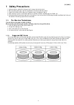
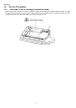
• When applying PbF solder to double layered boards, please check the component side for excess which may flow onto the
opposite side (See figure, below).
2.2.
Insulation Resistance Test
1. Unplug the power cord and short the two prongs of the plug with a jumper wire.
2. Turn on the power switch.
3. Measure the resistance value with an ohmmeter between the jumpered AC plug and each exposed metal cabinet part
(screw heads, control shafts, bottom frame, etc.).
Note: Some exposed parts may be isolated from the chassis by design. These will read infinity.
4. If the measurement is outside the specified limits, there is a possibility of a shock hazard.
2.3.
Battery Caution
CAUTION
Danger of explosion if the battery is incorrectly replaced. Replace only with the same or equivalent type recommended by the
manufacturer. Dispose of used batteries according to the manufacturer’s Instructions.
The lithium battery is a critical component (type No. CR2032). Please observe for the proper polarity and the exact location
when replacing it and soldering the replacement lithium battery in.
Содержание KX-FT932BR-B
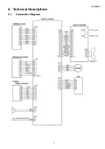
Страница 11: ...11 KX FT932BR B 6 Technical Descriptions 6 1 Connection Diagram ...
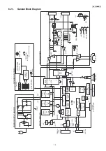
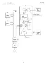
Страница 21: ...21 KX FT932BR B 6 4 2 Block Diagram ...
Страница 23: ...23 KX FT932BR B ...
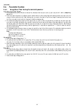
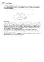
Страница 35: ...35 KX FT932BR B b Redundancy Compression Process Coding Mode This unit uses one dimensional MH format ...
Страница 60: ...60 KX FT932BR B 11 2 The Example of the Printed List 11 2 1 User Mode Example of a printed out list ...
Страница 61: ...61 KX FT932BR B 11 2 2 Service Mode Example of a printed out list ...
Страница 67: ...67 KX FT932BR B ...
Страница 68: ...68 KX FT932BR B CROSS REFERENCE Test Mode P 54 ...
Страница 69: ...69 KX FT932BR B CROSS REFERENCE Test Mode P 54 ...
Страница 70: ...70 KX FT932BR B CROSS REFERENCE Test Mode P 54 ...
Страница 71: ...71 KX FT932BR B ...
Страница 73: ...73 KX FT932BR B ...
Страница 74: ...74 KX FT932BR B ...
Страница 75: ...75 KX FT932BR B CROSS REFERENCE Test Mode P 54 ...
Страница 102: ...102 KX FT932BR B NG Wave pattern Note Refer to NG Example P 107 ...
Страница 104: ...104 KX FT932BR B I O and Pin No Diagram ...
Страница 106: ...106 KX FT932BR B ...
Страница 107: ...107 KX FT932BR B 12 5 5 3 NG Example ...
Страница 111: ...111 KX FT932BR B 12 5 7 2 Troubleshooting Flow Chart ...
Страница 115: ...115 KX FT932BR B 12 5 10 CIS Contact Image Sensor Section Refer to Scanning Block P 24 CROSS REFERENCE Test Mode P 54 ...
Страница 116: ...116 KX FT932BR B 12 5 11 Thermal Head Section Refer to Thermal Head P 22 ...
Страница 117: ...117 KX FT932BR B 13 Service Fixture Tools ...
Страница 120: ...120 KX FT932BR B 14 2 Disassembly Procedurel 14 2 1 How to Remove the Operation Panel Block ...
Страница 121: ...121 KX FT932BR B 14 2 2 How to Remove the Operation Board LCD and Platen Roller ...
Страница 122: ...122 KX FT932BR B 14 2 3 How to Remove the Separation Holder and Document Feed Support ...
Страница 123: ...123 KX FT932BR B 14 2 4 How to Remove the Image Sensor CIS and Feed Roller ...
Страница 124: ...124 KX FT932BR B 14 2 5 How to Remove the Lock Lever and Thermal Head ...
Страница 125: ...125 KX FT932BR B 14 2 6 How to Remove the Bottom Frame ...
Страница 126: ...126 KX FT932BR B 14 2 7 How to Remove the Analog Board Digital Board Power Supply Board and Power Cord ...
Страница 127: ...127 KX FT932BR B 14 2 8 How to Remove the Gear Block and Separation Roller 14 2 9 How to Remove the Motor of Gear Block ...
Страница 128: ...128 KX FT932BR B 14 2 10 Installation Position of the Lead Wires ...
Страница 134: ...134 KX FT932BR B 15 2 3 Mechanical Movements in the Main Operations 15 2 3 1 Idle Status ...
Страница 136: ...136 KX FT932BR B 15 2 3 4 Copying CROSS REFERENCE Sensor Section P 114 ...
Страница 140: ...140 KX FT932BR B 16 1 4 Power Supply Board ...
Страница 143: ...143 KX FT932BR B 16 3 Test Chart 16 3 1 ITU T No 1 Test Chart ...
Страница 144: ...144 KX FT932BR B 16 3 2 ITU T No 2 Test Chart ...
Страница 145: ...145 KX FT932BR B MEMO ...
Страница 152: ...152 KX FT932BR B MEMO ...
Страница 161: ...161 KX FT932BR B MEMO ...
Страница 163: ...163 KX FT932BR B 20 1 2 Upper Cabinet Section ...
Страница 164: ...164 KX FT932BR B 20 1 3 Lower Cabinet Section ...
Страница 165: ...165 KX FT932BR B 20 1 4 Gear Block Section ...
Страница 166: ...166 KX FT932BR B 20 1 5 Screws ...
Страница 167: ...167 KX FT932BR B 20 1 6 Accessories and Packing Materials ...


