101
KX-FT932BR-B
12.5.5.1. Digital Block Diagram
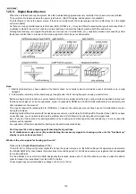
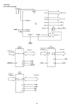
Digital board is including analog system. All analog signals (Telephone, CID and TAM) excepting Fax communications. Another
one is ASIC system for mechanical functions: Copy, Fax and UI (LCD/Key). And serial interface (UART) connects both systems.
Flash memory IC2 in the ASIC system is for software and also for user memory (settings, Phone book, CID memory) DRAM IC4
in the ASIC system is for work memory and also for fax memory.
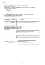
The signal lines that must be normal for the system to boot up are listed here [List 1].
For signal lines other than these, even if they malfunction they do not directly affect booting up the system.
Содержание KX-FT932BR-B
Страница 11: ...11 KX FT932BR B 6 Technical Descriptions 6 1 Connection Diagram ...
Страница 21: ...21 KX FT932BR B 6 4 2 Block Diagram ...
Страница 23: ...23 KX FT932BR B ...
Страница 35: ...35 KX FT932BR B b Redundancy Compression Process Coding Mode This unit uses one dimensional MH format ...
Страница 60: ...60 KX FT932BR B 11 2 The Example of the Printed List 11 2 1 User Mode Example of a printed out list ...
Страница 61: ...61 KX FT932BR B 11 2 2 Service Mode Example of a printed out list ...
Страница 67: ...67 KX FT932BR B ...
Страница 68: ...68 KX FT932BR B CROSS REFERENCE Test Mode P 54 ...
Страница 69: ...69 KX FT932BR B CROSS REFERENCE Test Mode P 54 ...
Страница 70: ...70 KX FT932BR B CROSS REFERENCE Test Mode P 54 ...
Страница 71: ...71 KX FT932BR B ...
Страница 73: ...73 KX FT932BR B ...
Страница 74: ...74 KX FT932BR B ...
Страница 75: ...75 KX FT932BR B CROSS REFERENCE Test Mode P 54 ...
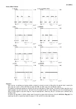
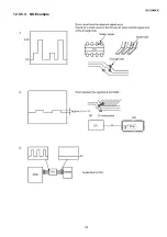
Страница 102: ...102 KX FT932BR B NG Wave pattern Note Refer to NG Example P 107 ...
Страница 104: ...104 KX FT932BR B I O and Pin No Diagram ...
Страница 106: ...106 KX FT932BR B ...
Страница 107: ...107 KX FT932BR B 12 5 5 3 NG Example ...
Страница 111: ...111 KX FT932BR B 12 5 7 2 Troubleshooting Flow Chart ...
Страница 115: ...115 KX FT932BR B 12 5 10 CIS Contact Image Sensor Section Refer to Scanning Block P 24 CROSS REFERENCE Test Mode P 54 ...
Страница 116: ...116 KX FT932BR B 12 5 11 Thermal Head Section Refer to Thermal Head P 22 ...
Страница 117: ...117 KX FT932BR B 13 Service Fixture Tools ...
Страница 120: ...120 KX FT932BR B 14 2 Disassembly Procedurel 14 2 1 How to Remove the Operation Panel Block ...
Страница 121: ...121 KX FT932BR B 14 2 2 How to Remove the Operation Board LCD and Platen Roller ...
Страница 122: ...122 KX FT932BR B 14 2 3 How to Remove the Separation Holder and Document Feed Support ...
Страница 123: ...123 KX FT932BR B 14 2 4 How to Remove the Image Sensor CIS and Feed Roller ...
Страница 124: ...124 KX FT932BR B 14 2 5 How to Remove the Lock Lever and Thermal Head ...
Страница 125: ...125 KX FT932BR B 14 2 6 How to Remove the Bottom Frame ...
Страница 126: ...126 KX FT932BR B 14 2 7 How to Remove the Analog Board Digital Board Power Supply Board and Power Cord ...
Страница 127: ...127 KX FT932BR B 14 2 8 How to Remove the Gear Block and Separation Roller 14 2 9 How to Remove the Motor of Gear Block ...
Страница 128: ...128 KX FT932BR B 14 2 10 Installation Position of the Lead Wires ...
Страница 134: ...134 KX FT932BR B 15 2 3 Mechanical Movements in the Main Operations 15 2 3 1 Idle Status ...
Страница 136: ...136 KX FT932BR B 15 2 3 4 Copying CROSS REFERENCE Sensor Section P 114 ...
Страница 140: ...140 KX FT932BR B 16 1 4 Power Supply Board ...
Страница 143: ...143 KX FT932BR B 16 3 Test Chart 16 3 1 ITU T No 1 Test Chart ...
Страница 144: ...144 KX FT932BR B 16 3 2 ITU T No 2 Test Chart ...
Страница 145: ...145 KX FT932BR B MEMO ...
Страница 152: ...152 KX FT932BR B MEMO ...
Страница 161: ...161 KX FT932BR B MEMO ...
Страница 163: ...163 KX FT932BR B 20 1 2 Upper Cabinet Section ...
Страница 164: ...164 KX FT932BR B 20 1 3 Lower Cabinet Section ...
Страница 165: ...165 KX FT932BR B 20 1 4 Gear Block Section ...
Страница 166: ...166 KX FT932BR B 20 1 5 Screws ...
Страница 167: ...167 KX FT932BR B 20 1 6 Accessories and Packing Materials ...

