51
4.7.3.2 Motion Detect Snapshot
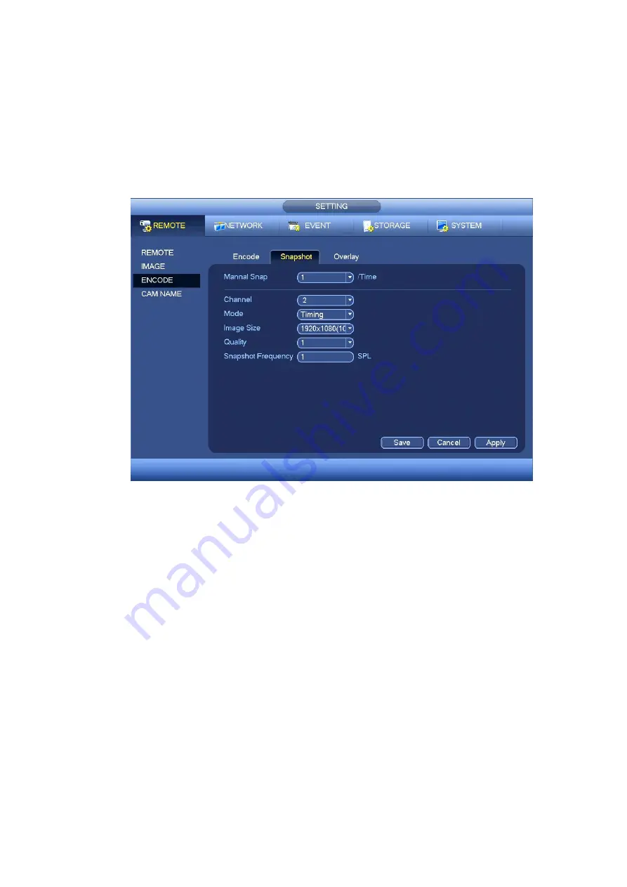
a) From Main menu->SETTING->REMOTE->ENCODE->Snapshot, you can go to snapshot
interface. See Figure 4-53.
b) In Figure 4-53, select trigger snapshot from the dropdown list and then set picture size, quality
and snapshot frequency. Click OK button to save current setup.
c) From Main menu->SETTING->EVENT->DETECT, here you can select motion detect type,
motion detect channel and then check the enable box. Please refer to chapter 4.7.3.1.
d) Click OK button to complete motion detect setup.
Figure 4-53
4.7.4
Alarm Record/Snapshot
4.7.4.1 Alarm Record
a) Before you set alarm setup information, please go to chapter 1 to connect alarm input and
alarm output cable (such as light, siren and etc).
b) The record priority is: Alarm>Motion detect>Regular.
In the main menu, from SETTING->EVENT-> ALARM, you can see alarm setup interface. See Figure
Alarm in: Here is for you to select channel number.
Event type: There are four types. Local input/network input/IPC external/IPC offline alarm.
Local input alarm: The alarm signal system detects from the alarm input port.
Network input alarm: It is the alarm signal from the network.
IPC external alarm: It is the on-off alarm signal from the front-end device and can activate the
local NVR.
IPC offline alarm: Once you select this item, system can generate an alarm when the front-end
IPC disconnects with the local NVR. The alarm can activate record, PTZ, snapshot and etc. The
alarm can last until the IPC and the NVR connection resumes.
Содержание k-nl304g
Страница 1: ...Network Video Recorder User s Manual Model No K NL304K G K NL308K G Version 1 0 2 ...
Страница 41: ...33 Figure 4 24 Tips On the navigation bar click to enable disable tour Click Save button to save current setup ...
Страница 58: ...50 Figure 4 51 Figure 4 52 ...
Страница 78: ...70 Figure 4 70 Figure 4 71 ...
Страница 79: ...71 Figure 4 72 Figure 4 73 ...
Страница 86: ...78 Figure 4 80 Figure 4 81 ...
Страница 87: ...79 Figure 4 82 Figure 4 83 ...
Страница 90: ...82 Figure 4 86 Figure 4 87 4 11 Network 4 11 1 Basic Setup ...
Страница 113: ...105 Figure 4 110 In Figure 4 110 click one HDD item the S M A R T interface is shown as in Figure 4 111 Figure 4 111 ...
Страница 116: ...108 Figure 4 114 Figure 4 115 ...
Страница 127: ...119 Figure 4 128 Figure 4 129 ...
Страница 162: ...154 Figure 5 40 Figure 5 41 ...
Страница 163: ...155 Figure 5 42 Figure 5 43 Figure 5 44 ...
Страница 171: ...163 Figure 5 56 Figure 5 57 Figure 5 58 Figure 5 59 Please refer to the following sheet for detailed information ...
Страница 173: ...165 Figure 5 60 Figure 5 61 ...


