4
1.4.
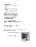
How to Discharge the Capacitor on Main P.C.B.
CAUTION:
1.
Be sure to discharge the capacitor on MAIN P.C.B..
2.
Be careful of the high voltage circuit on MAIN P.C.B. when servicing.
[Discharging Procedure]
1. Refer to the disassemble procedure and Remove the necessary parts/unit.
2. Put the insulation tube onto the lead part of Resistor (ERG5SJ102:1k
Ω
/5W).
(an equivalent type of resistor may be used.)
3. Put the resistor between both terminals of capacitor on MAIN P.C.B. for approx. 5 seconds.
4. After discharging confirm that the capacitor voltage is lower than 10V using a voltmeter.
Fig. F1
Содержание HX-WA20EB
Страница 10: ...10 4 Specifications ...
Страница 11: ...11 ...
Страница 12: ...12 ...
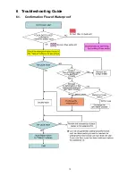
Страница 15: ...15 6 Troubleshooting Guide 6 1 Confirmation Flow of Waterproof ...
Страница 16: ...16 6 2 Airtight Inspection with Air Leak Tester ...
Страница 17: ...17 6 3 Air Leak Tester RFKZ0528 Operating Instruction ...
Страница 18: ...18 ...
Страница 19: ...19 ...
Страница 20: ...20 ...
Страница 24: ...24 8 3 1 Removal of the Top Ornament Fig D1 8 3 2 Removal of the Front Cabinet Unit Fig D2 ...
Страница 25: ...25 8 3 3 Removal of the Side L Cabinet Unit Fig D3 Fig D4 ...
Страница 26: ...26 Fig D5 Fig D6 8 3 4 Removal of the Battery Cover Fig D7 ...
Страница 27: ...27 Fig D8 8 3 5 Removal of the Waterproof Rubber Fig D9 Fig D10 ...
Страница 28: ...28 8 3 6 Removal of the Capacitor Capacitor Holder Fig D11 8 3 7 Removal of the Lens Unit Fig D12 ...
Страница 29: ...29 Fig D13 8 3 8 Removal of the Flash Unit Fig D14 8 3 9 Removal of the Main P C B and Battery Case Fig D15 ...
Страница 30: ...30 Fig D16 8 3 10 Removal of the Lens Holder Fig D17 8 3 11 Removal of the Speaker Fig D18 ...
Страница 31: ...31 8 3 12 Removal of the LCD Unit Fig D19 Fig D20 ...
Страница 32: ...32 Fig D21 Fig D22 ...
Страница 33: ...33 Fig D23 8 3 13 Removal of the Hinge Cover LCD Case T Unit Fig D24 Fig D25 ...
Страница 34: ...34 Fig D26 Fig D27 8 3 14 Removal of the LCD O Ring Fig D28 ...
Страница 35: ...35 Fig D29 8 3 15 Removal of the LCD Panel Fig D30 ...
Страница 36: ...36 Fig D31 8 3 16 Removal of the Mic Unit Monitor P C B Fig D32 Fig D33 ...
Страница 37: ...37 Fig D34 8 3 17 Removal of the LCD Hinge Unit Fig D35 ...
Страница 38: ...38 Fig D36 Fig D37 ...
Страница 39: ...39 8 3 18 Removal of the Switch Unit Fig D38 Fig D39 ...
Страница 40: ...40 Fig D40 ...
Страница 43: ...43 10 Maintenance 10 1 Regular Maintenance Flow ...
Страница 44: ...44 10 2 Component Kits of Waterproof ...
Страница 50: ...Model No HX WA20 Schematic Diagram Note ...
Страница 51: ...Model No HX WA20 Parts List Note ...
Страница 52: ...Model No HX WA20 Main DMA Schematic Diagram Main P C B ...
Страница 53: ...Model No HX WA20 Main PWA Schematic Diagram Main P C B ...
Страница 54: ...Model No HX WA20 Main STA Schematic Diagram Main P C B ...
Страница 55: ...Model No HX WA20 Monitor Schematic Diagram Monitor P C B ...
Страница 56: ...Model No HX WA20 Main P C B Component Side ...
Страница 57: ...Model No HX WA20 Main P C B Foil Side ...
Страница 58: ...Model No HX WA20 Monitor P C B Component Side ...
Страница 59: ...Model No HX WA20 Monitor P C B Foil Side ...
Страница 66: ...Model No HX WA20 Frame and Casing Section 1 ...
Страница 67: ...Model No HX WA20 Frame and Casing Section 2 ...
Страница 68: ...Model No HX WA20 Packing Parts and Accessories Section ...


