23
8.2.
PCB Location
8.3.
Disassembly Procedure
No.
Item
Fig
Removal
1
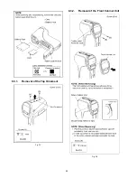
Top Ornament
Fig. D1
2 Screws (A)
Top Ornament
2
Front Cabinet Unit
Fig. D2
2 Screws (B)
Front Cabinet Unit
3
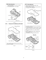
Side-L Cabinet Unit
Fig. D3
3 Screws (C)
5 Screws (D)
Fig. D4
3 Locking tabs
Side-L Cabinet Unit
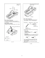
Fig. D5
NOTE: (When Installing)
Fig. D6
NOTE: (When Replacing)
4
Battery Cover
Fig. D7
Shaft
Battery Cover Spring
Battery Cover
Fig. D8
NOTE: (When Replacing)
5
Waterproof Rubber
Fig. D9
Waterproof Rubber
Fig. D10
NOTE: (When Replacing)
6
Capacitor
Capacitor Holder
Fig. D11
2 Screws (E)
2 Solders
Capacitor
Capacitor Holder
7
Lens Unit
Fig. D12
2 Cushions
3 Screws (F)
1 Screw (G)
Heat Sink
CN901 (Flex)
CN951 (Flex)
Fig. D13
Lens Unit
2 Cushions
8
Flash Unit
Fig. D14
1 Screw (H)
4 Solders
1 Rib
Flash Unit
9
Main P.C.B.
Battery Case
Fig. D15
1 Screw (I)
1 Screw (J)
2 Solders
CN103 (Connector)
CN301 (Flex)
2 Screws (K)
3 Solders
Fig. D16
Battery Case
Earth Plate
Main P.C.B.
10
Lens Holder
Fig. D17
3 Screws (L)
Lens Holder
11
Speaker
Fig. D18
1 Screw (M)
Speaker
Speaker Holder
12
LCD Unit
Fig. D19
2 Screws (N)
2 O-Rings
Fig. D20
2 Screws (O)
Side-R Cover
Side-R Ornament
Rear Ornament
Fig. D21
2 Screws (P)
2 O-Rings
Fig. D22
LCD Unit
Fig. D23
NOTE: (When Installing)
13
Hinge Cover
LCD Case(T) Unit
Fig. D24
1 Screw (Q)
Fig. D25
Hinge Cover
2 LCD Covers
2 Screws (R)
2 Screws (S)
2 Screws (T)
2 Screws (U)
Fig. D26
LCD Case(T) Unit
Fig. D27
NOTE: (When Installing)
14
LCD O-Ring
Fig. D28
LCD O-Ring
Fig. D29
NOTE: (When Replacing)
15
LCD Panel
Fig. D30
CN172 (Connector)
CN173 (Flex)
3 Screws (V)
LCD Case (B) Unit
CN171 (Flex)
Fig. D31
LCD Panel
16
Mic Unit
Monitor P.C.B.
Fig. D32
4 Solders
2 Ribs
Fig. D33
Built-in Microphones
Mic Holder Unit
Fig. D34
2 Screws (W)
1 Screw (X)
Monitor P.C.B.
17
LCD Hinge Unit
Fig. D35
1 Locking tab
Fig. D36
Wire Unit
LCD Hinge Unit
Fig. D37
NOTE: (When Installing)
18
Switch Unit
Fig. D38
Photoshot Button
Recording Button
4 Screws (Y)
Heat Sink
Fig. D39
Button Plate
Switch Unit
Fig. D40
NOTE: (When Installing)
No.
Item
Fig
Removal
Содержание HX-WA20EB
Страница 10: ...10 4 Specifications ...
Страница 11: ...11 ...
Страница 12: ...12 ...
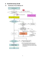
Страница 15: ...15 6 Troubleshooting Guide 6 1 Confirmation Flow of Waterproof ...
Страница 16: ...16 6 2 Airtight Inspection with Air Leak Tester ...
Страница 17: ...17 6 3 Air Leak Tester RFKZ0528 Operating Instruction ...
Страница 18: ...18 ...
Страница 19: ...19 ...
Страница 20: ...20 ...
Страница 24: ...24 8 3 1 Removal of the Top Ornament Fig D1 8 3 2 Removal of the Front Cabinet Unit Fig D2 ...
Страница 25: ...25 8 3 3 Removal of the Side L Cabinet Unit Fig D3 Fig D4 ...
Страница 26: ...26 Fig D5 Fig D6 8 3 4 Removal of the Battery Cover Fig D7 ...
Страница 27: ...27 Fig D8 8 3 5 Removal of the Waterproof Rubber Fig D9 Fig D10 ...
Страница 28: ...28 8 3 6 Removal of the Capacitor Capacitor Holder Fig D11 8 3 7 Removal of the Lens Unit Fig D12 ...
Страница 29: ...29 Fig D13 8 3 8 Removal of the Flash Unit Fig D14 8 3 9 Removal of the Main P C B and Battery Case Fig D15 ...
Страница 30: ...30 Fig D16 8 3 10 Removal of the Lens Holder Fig D17 8 3 11 Removal of the Speaker Fig D18 ...
Страница 31: ...31 8 3 12 Removal of the LCD Unit Fig D19 Fig D20 ...
Страница 32: ...32 Fig D21 Fig D22 ...
Страница 33: ...33 Fig D23 8 3 13 Removal of the Hinge Cover LCD Case T Unit Fig D24 Fig D25 ...
Страница 34: ...34 Fig D26 Fig D27 8 3 14 Removal of the LCD O Ring Fig D28 ...
Страница 35: ...35 Fig D29 8 3 15 Removal of the LCD Panel Fig D30 ...
Страница 36: ...36 Fig D31 8 3 16 Removal of the Mic Unit Monitor P C B Fig D32 Fig D33 ...
Страница 37: ...37 Fig D34 8 3 17 Removal of the LCD Hinge Unit Fig D35 ...
Страница 38: ...38 Fig D36 Fig D37 ...
Страница 39: ...39 8 3 18 Removal of the Switch Unit Fig D38 Fig D39 ...
Страница 40: ...40 Fig D40 ...
Страница 43: ...43 10 Maintenance 10 1 Regular Maintenance Flow ...
Страница 44: ...44 10 2 Component Kits of Waterproof ...
Страница 50: ...Model No HX WA20 Schematic Diagram Note ...
Страница 51: ...Model No HX WA20 Parts List Note ...
Страница 52: ...Model No HX WA20 Main DMA Schematic Diagram Main P C B ...
Страница 53: ...Model No HX WA20 Main PWA Schematic Diagram Main P C B ...
Страница 54: ...Model No HX WA20 Main STA Schematic Diagram Main P C B ...
Страница 55: ...Model No HX WA20 Monitor Schematic Diagram Monitor P C B ...
Страница 56: ...Model No HX WA20 Main P C B Component Side ...
Страница 57: ...Model No HX WA20 Main P C B Foil Side ...
Страница 58: ...Model No HX WA20 Monitor P C B Component Side ...
Страница 59: ...Model No HX WA20 Monitor P C B Foil Side ...
Страница 66: ...Model No HX WA20 Frame and Casing Section 1 ...
Страница 67: ...Model No HX WA20 Frame and Casing Section 2 ...
Страница 68: ...Model No HX WA20 Packing Parts and Accessories Section ...

