9
3.5.
Formatting
3.6.
Baking of IC and P.C.B.
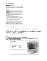
The baking mentioned here is the way of dehumidification of IC and P.C.B..
It's possible to improve the success rate of IC replacement for repair by baking of IC and P.C.B..
When replacing the hygroscopic IC and P.C.B., the problem of IC crack or foil pattern breaking in the P.C.B. might sometimes occur
by rapid heating.
For that case, please test the baking of IC and P.C.B. before replacing IC in order to prevent the above mentioned problem.
IC( Service parts) and P.C.B. should be put in the heater together.
Reference value for baking temperature and time is as follows.
• Baking temperature and time (Hour)
80
°
C / 12 hour
[ Note ]
This setting value of temperature and time (Hour) is actually used in Japan.
An appropriate setting value changes depending on the environmental condition of the work place in your country.
However, the setting temperature must not exceed 125
°
C.
Содержание HX-WA20EB
Страница 10: ...10 4 Specifications ...
Страница 11: ...11 ...
Страница 12: ...12 ...
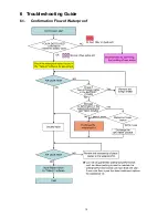
Страница 15: ...15 6 Troubleshooting Guide 6 1 Confirmation Flow of Waterproof ...
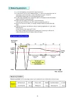
Страница 16: ...16 6 2 Airtight Inspection with Air Leak Tester ...
Страница 17: ...17 6 3 Air Leak Tester RFKZ0528 Operating Instruction ...
Страница 18: ...18 ...
Страница 19: ...19 ...
Страница 20: ...20 ...
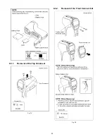
Страница 24: ...24 8 3 1 Removal of the Top Ornament Fig D1 8 3 2 Removal of the Front Cabinet Unit Fig D2 ...
Страница 25: ...25 8 3 3 Removal of the Side L Cabinet Unit Fig D3 Fig D4 ...
Страница 26: ...26 Fig D5 Fig D6 8 3 4 Removal of the Battery Cover Fig D7 ...
Страница 27: ...27 Fig D8 8 3 5 Removal of the Waterproof Rubber Fig D9 Fig D10 ...
Страница 28: ...28 8 3 6 Removal of the Capacitor Capacitor Holder Fig D11 8 3 7 Removal of the Lens Unit Fig D12 ...
Страница 29: ...29 Fig D13 8 3 8 Removal of the Flash Unit Fig D14 8 3 9 Removal of the Main P C B and Battery Case Fig D15 ...
Страница 30: ...30 Fig D16 8 3 10 Removal of the Lens Holder Fig D17 8 3 11 Removal of the Speaker Fig D18 ...
Страница 31: ...31 8 3 12 Removal of the LCD Unit Fig D19 Fig D20 ...
Страница 32: ...32 Fig D21 Fig D22 ...
Страница 33: ...33 Fig D23 8 3 13 Removal of the Hinge Cover LCD Case T Unit Fig D24 Fig D25 ...
Страница 34: ...34 Fig D26 Fig D27 8 3 14 Removal of the LCD O Ring Fig D28 ...
Страница 35: ...35 Fig D29 8 3 15 Removal of the LCD Panel Fig D30 ...
Страница 36: ...36 Fig D31 8 3 16 Removal of the Mic Unit Monitor P C B Fig D32 Fig D33 ...
Страница 37: ...37 Fig D34 8 3 17 Removal of the LCD Hinge Unit Fig D35 ...
Страница 38: ...38 Fig D36 Fig D37 ...
Страница 39: ...39 8 3 18 Removal of the Switch Unit Fig D38 Fig D39 ...
Страница 40: ...40 Fig D40 ...
Страница 43: ...43 10 Maintenance 10 1 Regular Maintenance Flow ...
Страница 44: ...44 10 2 Component Kits of Waterproof ...
Страница 50: ...Model No HX WA20 Schematic Diagram Note ...
Страница 51: ...Model No HX WA20 Parts List Note ...
Страница 52: ...Model No HX WA20 Main DMA Schematic Diagram Main P C B ...
Страница 53: ...Model No HX WA20 Main PWA Schematic Diagram Main P C B ...
Страница 54: ...Model No HX WA20 Main STA Schematic Diagram Main P C B ...
Страница 55: ...Model No HX WA20 Monitor Schematic Diagram Monitor P C B ...
Страница 56: ...Model No HX WA20 Main P C B Component Side ...
Страница 57: ...Model No HX WA20 Main P C B Foil Side ...
Страница 58: ...Model No HX WA20 Monitor P C B Component Side ...
Страница 59: ...Model No HX WA20 Monitor P C B Foil Side ...
Страница 66: ...Model No HX WA20 Frame and Casing Section 1 ...
Страница 67: ...Model No HX WA20 Frame and Casing Section 2 ...
Страница 68: ...Model No HX WA20 Packing Parts and Accessories Section ...


