6
2.3.
How to Replace the Lithium Battery
2.3.1.
Replacement Procedure
1. Remove the MONITOR P.C.B.. (Refer to Disassembly Procedures.)
2. Unsolder the each soldering point of electric lead terminal for Lithium battery (Ref. No. “Z6301” at component side of MONI-
TOR P.C.B.) and remove the Lithium battery together with electric lead terminal. Then replace it into new one.
NOTE:
The Type No. VU6450989551 includes electric lead terminals.
NOTE:
This Lithium battery is a critical component.
It must never be subjected to excessive heat or discharge.
It must therefore only be fitted in requirement designed specifically for its use.
Replacement batteries must be of same type and manufacture.
They must be fitted in the same manner and location as the original battery, with the correct polarity contacts observed.
Do not attempt to re-charge the old battery or re-use it for any other purpose.
It should be disposed of in waste products destined for burial rather than incineration.
NOTE:
Above caution is applicable for a battery pack which is for HX-WA20 series, as well.
Содержание HX-WA20EB
Страница 10: ...10 4 Specifications ...
Страница 11: ...11 ...
Страница 12: ...12 ...
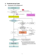
Страница 15: ...15 6 Troubleshooting Guide 6 1 Confirmation Flow of Waterproof ...
Страница 16: ...16 6 2 Airtight Inspection with Air Leak Tester ...
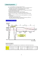
Страница 17: ...17 6 3 Air Leak Tester RFKZ0528 Operating Instruction ...
Страница 18: ...18 ...
Страница 19: ...19 ...
Страница 20: ...20 ...
Страница 24: ...24 8 3 1 Removal of the Top Ornament Fig D1 8 3 2 Removal of the Front Cabinet Unit Fig D2 ...
Страница 25: ...25 8 3 3 Removal of the Side L Cabinet Unit Fig D3 Fig D4 ...
Страница 26: ...26 Fig D5 Fig D6 8 3 4 Removal of the Battery Cover Fig D7 ...
Страница 27: ...27 Fig D8 8 3 5 Removal of the Waterproof Rubber Fig D9 Fig D10 ...
Страница 28: ...28 8 3 6 Removal of the Capacitor Capacitor Holder Fig D11 8 3 7 Removal of the Lens Unit Fig D12 ...
Страница 29: ...29 Fig D13 8 3 8 Removal of the Flash Unit Fig D14 8 3 9 Removal of the Main P C B and Battery Case Fig D15 ...
Страница 30: ...30 Fig D16 8 3 10 Removal of the Lens Holder Fig D17 8 3 11 Removal of the Speaker Fig D18 ...
Страница 31: ...31 8 3 12 Removal of the LCD Unit Fig D19 Fig D20 ...
Страница 32: ...32 Fig D21 Fig D22 ...
Страница 33: ...33 Fig D23 8 3 13 Removal of the Hinge Cover LCD Case T Unit Fig D24 Fig D25 ...
Страница 34: ...34 Fig D26 Fig D27 8 3 14 Removal of the LCD O Ring Fig D28 ...
Страница 35: ...35 Fig D29 8 3 15 Removal of the LCD Panel Fig D30 ...
Страница 36: ...36 Fig D31 8 3 16 Removal of the Mic Unit Monitor P C B Fig D32 Fig D33 ...
Страница 37: ...37 Fig D34 8 3 17 Removal of the LCD Hinge Unit Fig D35 ...
Страница 38: ...38 Fig D36 Fig D37 ...
Страница 39: ...39 8 3 18 Removal of the Switch Unit Fig D38 Fig D39 ...
Страница 40: ...40 Fig D40 ...
Страница 43: ...43 10 Maintenance 10 1 Regular Maintenance Flow ...
Страница 44: ...44 10 2 Component Kits of Waterproof ...
Страница 50: ...Model No HX WA20 Schematic Diagram Note ...
Страница 51: ...Model No HX WA20 Parts List Note ...
Страница 52: ...Model No HX WA20 Main DMA Schematic Diagram Main P C B ...
Страница 53: ...Model No HX WA20 Main PWA Schematic Diagram Main P C B ...
Страница 54: ...Model No HX WA20 Main STA Schematic Diagram Main P C B ...
Страница 55: ...Model No HX WA20 Monitor Schematic Diagram Monitor P C B ...
Страница 56: ...Model No HX WA20 Main P C B Component Side ...
Страница 57: ...Model No HX WA20 Main P C B Foil Side ...
Страница 58: ...Model No HX WA20 Monitor P C B Component Side ...
Страница 59: ...Model No HX WA20 Monitor P C B Foil Side ...
Страница 66: ...Model No HX WA20 Frame and Casing Section 1 ...
Страница 67: ...Model No HX WA20 Frame and Casing Section 2 ...
Страница 68: ...Model No HX WA20 Packing Parts and Accessories Section ...


