


2
TABLE OF CONTENTS
PAGE
PAGE
1 Safety Precautions
-----------------------------------------------
1.1. General Guidelines ----------------------------------------3
1.2. Leakage Current Cold Check ---------------------------3
1.3. Leakage Current Hot Check (See Figure 1.)--------3
1.4. How to Discharge the Capacitor on Flash
P.C.B.----------------------------------------------------------4
2 Warning
--------------------------------------------------------------
2.1. Prevention of Electrostatic Discharge (ESD)
to Electrostatically Sensitive (ES) Devices ----------5
2.2. How to Recycle the Lithium Ion Battery (U.S.
Only)-----------------------------------------------------------5
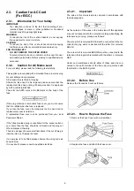
2.3. Caution for AC Cord (For E/GC) -----------------------6
2.4. How to Replace the Lithium Battery-------------------7
3 Service Navigation
------------------------------------------------
3.1. Introduction --------------------------------------------------8
3.2. General Description About Lead Free Solder
(PbF) ----------------------------------------------------------8
3.3. Important Notice 1:(Other than U.S.A. and
Canadian Market) ------------------------------------------8
3.4. How to Define the Model Suffix (NTSC or PAL
model)---------------------------------------------------------8
3.5. Formatting-------------------------------------------------- 10
4 Specifications
----------------------------------------------------
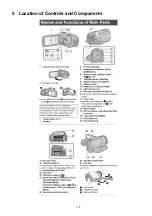
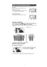
5 Location of Controls and Components
------------------
6 Service Mode
-----------------------------------------------------
6.1. Built-in Memory Self Check Execution (HC-
X900M only) ----------------------------------------------- 19
6.2. Lock Search History Indication ----------------------- 19
6.3. Power ON Self Check Result Display--------------- 20
6.4. Forced full flash emission ------------------------------ 21
6.5. Erasing the lock histories ------------------------------ 21
6.6. Camera data indications while the video
playback ---------------------------------------------------- 22
7 Service Fixture & Tools
---------------------------------------
7.1. When Replacing the Main P.C.B. -------------------- 23
7.2. Service Position ------------------------------------------ 23
8 Disassembly and Assembly Instructions
---------------
8.1. Disassembly Flow Chart for the Unit ---------------- 25
8.2. P.C.B. Location ------------------------------------------- 25
8.3. Disassembly Procedure for the Unit----------------- 26
9 Measurements and Adjustments
--------------------------
9.1. Electric Adjustment -------------------------------------- 45
10 Factory Setting
---------------------------------------------------
10.1. How To Turn On The Factory Settings? ------------ 47
10.2. What is The Factory Settings?------------------------ 48
11 Block Diagram
---------------------------------------------------
11.1. Overall Block Diagram ---------------------------------- 49
11.2. System Control Block Diagram ----------------------- 50
11.3. Video/Audio Process Block Diagram (1/2)--------- 51
11.4. Video/Audio Process Block Diagram (2/2)--------- 52
11.5. Camera Block Diagram--------------------------------- 53
11.6. Lens Drive Block Diagram----------------------------- 54
11.7. Power Block Diagram----------------------------------- 55
12 Wiring Connection Diagram
--------------------------------
12.1. Interconnection Diagram------------------------------- 56
Содержание HC-X900EB
Страница 10: ...10 3 5 Formatting ...
Страница 11: ...11 4 Specifications ...
Страница 12: ...12 ...
Страница 13: ...13 ...
Страница 14: ...14 ...
Страница 15: ...15 5 Location of Controls and Components ...
Страница 16: ...16 ...
Страница 17: ...17 ...
Страница 28: ...28 8 3 1 Removal of the Side Case L Unit Fig D1 Fig D2 8 3 2 Removal of the SD OP P C B Fig D3 ...
Страница 29: ...29 8 3 3 Removal of the Cover Board Unit Fig D4 8 3 4 Removal of the ESD P C B HC X900M only Fig D5 ...
Страница 30: ...30 8 3 5 Removal of the Top OP Unit Fig D6 Fig D7 ...
Страница 32: ...32 8 3 9 Removal of the Battery Catcher P C B Fig D11 8 3 10 Removal of the Main P C B Fig D12 ...
Страница 33: ...33 Fig D13 8 3 11 Removal of the Flash P C B Fig D14 ...
Страница 34: ...34 8 3 12 Removal of the Fan Motor Fig D15 8 3 13 Removal of the LCD Case T Unit Fig D16 Fig D17 ...
Страница 35: ...35 Fig D18 8 3 14 Removal of the Monitor P C B Fig D19 Fig D20 8 3 15 Removal of the LCD Panel Unit Fig D21 ...
Страница 36: ...36 Fig D22 8 3 16 Removal of the Front P C B Fig D23 8 3 17 Removal of the Barrier Motor Unit Fig D24 ...
Страница 37: ...37 8 3 18 Removal of the Barrier Case Unit Fig D25 Fig D26 ...
Страница 39: ...39 Fig D30 Fig D31 Fig D32 ...
Страница 40: ...40 8 3 21 Removal of the EVF Lens Holder Unit Fig D33 Fig D34 ...
Страница 41: ...41 8 3 22 Removal of the Top Frame Fig D35 8 3 23 Removal of the Zoom Operation Unit Fig D36 Fig D37 ...
Страница 42: ...42 8 3 24 Removal of the S S Case Unit Fig D38 8 3 25 Removal of the DC Jack P C B Fig D39 Fig D40 ...
Страница 44: ...44 8 3 29 Removal of the MOS Unit Fig D44 8 3 30 Removal of the Stepping Motor Fig D45 ...
Страница 58: ...Model No HC X900MP MPC MPU MEG MEP MEB MGC MEE MGN MGK HC X900EG EF EP EB GC EE GN HC X909EG Parts List Note 6 ...
Страница 63: ...Model No HC X900MP MPC MPU MEG MEP MEB MGC MEE MGN MGK HC X900EG EF EP EB GC EE GN HC X909EG AVIO Main P C B 6 ...
Страница 115: ...Model No HC X900MP MPC MPU MEG MEP MEB MGC MEE MGN MGK HC X900EG EF EP EB GC EE GN HC X909EG EVF Section 6 ...
Страница 116: ...Model No HC X900MP MPC MPU MEG MEP MEB MGC MEE MGN MGK HC X900EG EF EP EB GC EE GN HC X909EG LCD Section 6 ...


