


21
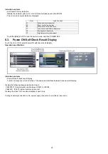
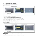
6.4.
Forced full flash emission
Touch the [ 9 ] of LCD, select Forced full flash execution.
Operation specifications
Indication contents
• Discharging the capacitor without using register.
Forced full flash emission for charge capacitor completely discharge.
To prevent electric shock, we recommend enforcement before disassembling.
Cutting of battery connection or AC power supply connection to end the service mode.
6.5.
Erasing the lock histories
Touch the [ 10 ] of LCD, select erasing the lock histories execution.
Operation specifications
Indication contents
• Erasing the error histories stored in EEPROM. (working time is not erased)
Cutting of battery connection or AC power supply connection to end the service mode.
Содержание HC-X900EB
Страница 10: ...10 3 5 Formatting ...
Страница 11: ...11 4 Specifications ...
Страница 12: ...12 ...
Страница 13: ...13 ...
Страница 14: ...14 ...
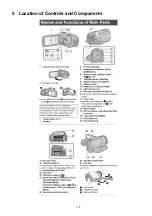
Страница 15: ...15 5 Location of Controls and Components ...
Страница 16: ...16 ...
Страница 17: ...17 ...
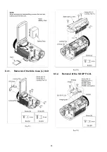
Страница 28: ...28 8 3 1 Removal of the Side Case L Unit Fig D1 Fig D2 8 3 2 Removal of the SD OP P C B Fig D3 ...
Страница 29: ...29 8 3 3 Removal of the Cover Board Unit Fig D4 8 3 4 Removal of the ESD P C B HC X900M only Fig D5 ...
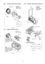
Страница 30: ...30 8 3 5 Removal of the Top OP Unit Fig D6 Fig D7 ...
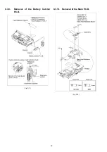
Страница 32: ...32 8 3 9 Removal of the Battery Catcher P C B Fig D11 8 3 10 Removal of the Main P C B Fig D12 ...
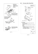
Страница 33: ...33 Fig D13 8 3 11 Removal of the Flash P C B Fig D14 ...
Страница 34: ...34 8 3 12 Removal of the Fan Motor Fig D15 8 3 13 Removal of the LCD Case T Unit Fig D16 Fig D17 ...
Страница 35: ...35 Fig D18 8 3 14 Removal of the Monitor P C B Fig D19 Fig D20 8 3 15 Removal of the LCD Panel Unit Fig D21 ...
Страница 36: ...36 Fig D22 8 3 16 Removal of the Front P C B Fig D23 8 3 17 Removal of the Barrier Motor Unit Fig D24 ...
Страница 37: ...37 8 3 18 Removal of the Barrier Case Unit Fig D25 Fig D26 ...
Страница 39: ...39 Fig D30 Fig D31 Fig D32 ...
Страница 40: ...40 8 3 21 Removal of the EVF Lens Holder Unit Fig D33 Fig D34 ...
Страница 41: ...41 8 3 22 Removal of the Top Frame Fig D35 8 3 23 Removal of the Zoom Operation Unit Fig D36 Fig D37 ...
Страница 42: ...42 8 3 24 Removal of the S S Case Unit Fig D38 8 3 25 Removal of the DC Jack P C B Fig D39 Fig D40 ...
Страница 44: ...44 8 3 29 Removal of the MOS Unit Fig D44 8 3 30 Removal of the Stepping Motor Fig D45 ...
Страница 58: ...Model No HC X900MP MPC MPU MEG MEP MEB MGC MEE MGN MGK HC X900EG EF EP EB GC EE GN HC X909EG Parts List Note 6 ...
Страница 63: ...Model No HC X900MP MPC MPU MEG MEP MEB MGC MEE MGN MGK HC X900EG EF EP EB GC EE GN HC X909EG AVIO Main P C B 6 ...
Страница 115: ...Model No HC X900MP MPC MPU MEG MEP MEB MGC MEE MGN MGK HC X900EG EF EP EB GC EE GN HC X909EG EVF Section 6 ...
Страница 116: ...Model No HC X900MP MPC MPU MEG MEP MEB MGC MEE MGN MGK HC X900EG EF EP EB GC EE GN HC X909EG LCD Section 6 ...


