


3
1 Safety Precautions
1.1.
General Guidelines
1.
IMPORTANT SAFETY NOTICE
There are special components used in this equipment
which are important for safety. These parts are marked by
in the Schematic Diagrams, Circuit Board Layout,
Exploded Views and Replacement Parts List. It is essen-
tial that these critical parts should be replaced with manu-
facturer’s specified parts to prevent X-RADIATION,
shock, fire, or other hazards. Do not modify the original
design without permission of manufacturer.
2. An Isolation Transformer should always be used during
the servicing of AC Adaptor whose chassis is not isolated
from the AC power line. Use a transformer of adequate
power rating as this protects the technician from acci-
dents resulting in personal injury from electrical shocks. It
will also protect AC Adaptor from being damaged by acci-
dental shorting that may occur during servicing.
3. When servicing, observe the original lead dress. If a short
circuit is found, replace all parts which have been over-
heated or damaged by the short circuit.
4. After servicing, see to it that all the protective devices
such as insulation barriers, insulation papers shields are
properly installed.
5. After servicing, make the following leakage current
checks to prevent the customer from being exposed to
shock hazards.
1.2.
Leakage Current Cold Check
1. Unplug the AC cord and connect a jumper between the
two prongs on the plug.
2. Measure the resistance value, with an ohmmeter,
between the jumpered AC plug and each exposed metal-
lic cabinet part on the equipment such as screwheads,
connectors, control shafts, etc. When the exposed metal-
lic part has a return path to the chassis, the reading
should be between 1 M
Ω
and 5.2 M
Ω
. When the exposed
metal does not have a return path to the chassis, the
reading must be infinity.
1.3.
Leakage Current Hot Check
(See Figure 1.)
1. Plug the AC cord directly into the AC outlet. Do not use
an isolation transformer for this check.
2. Connect a 1.5 k
Ω
, 10 W resistor, in parallel with a 0.15
µ
F
capacitor, between each exposed metallic part on the set
and a good earth ground, as shown in Figure 1.
3. Use an AC voltmeter, with 1 k
Ω
/V or more sensitivity, to
measure the potential across the resistor.
4. Check each exposed metallic part, and measure the volt-
age at each point.
5. Reverse the AC plug in the AC outlet and repeat each of
the above measurements.
6. The potential at any point should not exceed 0.75 V RMS.
A leakage current tester (Simpson Model 229 or equiva-
lent) may be used to make the hot checks, leakage cur-
rent must not exceed 1/2 mA. In case a measurement is
outside of the limits specified, there is a possibility of a
shock hazard, and the equipment should be repaired and
rechecked before it is returned to the customer.
Figure. 1
Содержание HC-X900EB
Страница 10: ...10 3 5 Formatting ...
Страница 11: ...11 4 Specifications ...
Страница 12: ...12 ...
Страница 13: ...13 ...
Страница 14: ...14 ...
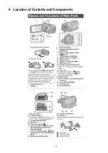
Страница 15: ...15 5 Location of Controls and Components ...
Страница 16: ...16 ...
Страница 17: ...17 ...
Страница 28: ...28 8 3 1 Removal of the Side Case L Unit Fig D1 Fig D2 8 3 2 Removal of the SD OP P C B Fig D3 ...
Страница 29: ...29 8 3 3 Removal of the Cover Board Unit Fig D4 8 3 4 Removal of the ESD P C B HC X900M only Fig D5 ...
Страница 30: ...30 8 3 5 Removal of the Top OP Unit Fig D6 Fig D7 ...
Страница 32: ...32 8 3 9 Removal of the Battery Catcher P C B Fig D11 8 3 10 Removal of the Main P C B Fig D12 ...
Страница 33: ...33 Fig D13 8 3 11 Removal of the Flash P C B Fig D14 ...
Страница 34: ...34 8 3 12 Removal of the Fan Motor Fig D15 8 3 13 Removal of the LCD Case T Unit Fig D16 Fig D17 ...
Страница 35: ...35 Fig D18 8 3 14 Removal of the Monitor P C B Fig D19 Fig D20 8 3 15 Removal of the LCD Panel Unit Fig D21 ...
Страница 36: ...36 Fig D22 8 3 16 Removal of the Front P C B Fig D23 8 3 17 Removal of the Barrier Motor Unit Fig D24 ...
Страница 37: ...37 8 3 18 Removal of the Barrier Case Unit Fig D25 Fig D26 ...
Страница 39: ...39 Fig D30 Fig D31 Fig D32 ...
Страница 40: ...40 8 3 21 Removal of the EVF Lens Holder Unit Fig D33 Fig D34 ...
Страница 41: ...41 8 3 22 Removal of the Top Frame Fig D35 8 3 23 Removal of the Zoom Operation Unit Fig D36 Fig D37 ...
Страница 42: ...42 8 3 24 Removal of the S S Case Unit Fig D38 8 3 25 Removal of the DC Jack P C B Fig D39 Fig D40 ...
Страница 44: ...44 8 3 29 Removal of the MOS Unit Fig D44 8 3 30 Removal of the Stepping Motor Fig D45 ...
Страница 58: ...Model No HC X900MP MPC MPU MEG MEP MEB MGC MEE MGN MGK HC X900EG EF EP EB GC EE GN HC X909EG Parts List Note 6 ...
Страница 63: ...Model No HC X900MP MPC MPU MEG MEP MEB MGC MEE MGN MGK HC X900EG EF EP EB GC EE GN HC X909EG AVIO Main P C B 6 ...
Страница 115: ...Model No HC X900MP MPC MPU MEG MEP MEB MGC MEE MGN MGK HC X900EG EF EP EB GC EE GN HC X909EG EVF Section 6 ...
Страница 116: ...Model No HC X900MP MPC MPU MEG MEP MEB MGC MEE MGN MGK HC X900EG EF EP EB GC EE GN HC X909EG LCD Section 6 ...


