


8
3 Service Navigation
3.1.
Introduction
This service manual contains technical information, which allow service personnel’s to understand and service this model.
Please place orders using the parts list and not the drawing reference numbers.
If the circuit is changed or modified, the information will be followed by service manual to be controlled with original service manual.
3.2.
General Description About Lead Free Solder (PbF)
The lead free solder has been used in the mounting process of all electrical components on the printed circuit boards used for this
equipment in considering the globally environmental conservation.
The normal solder is the alloy of tin (Sn) and lead (Pb). On the other hand, the lead free solder is the alloy mainly consists of tin
(Sn), silver (Ag) and Copper (Cu), and the melting point of the lead free solder is higher approx.30
°
C (86
°
F) more than that of the
normal solder.
Distinction of P.C.B. Lead Free Solder being used
Service caution for repair work using Lead Free Solder (PbF)
• The lead free solder has to be used when repairing the equipment for which the lead free solder is used.
(Definition: The letter of “PbF” is printed on the P.C.B. using the lead free solder.)
• To put lead free solder, it should be well molten and mixed with the original lead free solder.
• Remove the remaining lead free solder on the P.C.B. cleanly for soldering of the new IC.
• Since the melting point of the lead free solder is higher than that of the normal lead solder, it takes the longer time to melt the
lead free solder.
• Use the soldering iron (more than 70W) equipped with the temperature control after setting the temperature at 350±30
°
C
(662±86
°
F).
Recommended Lead Free Solder (Service Parts Route.)
• The following 3 types of lead free solder are available through the service parts route.
RFKZ03D01KS-----------(0.3mm 100g Reel)
RFKZ06D01KS-----------(0.6mm 100g Reel)
RFKZ10D01KS-----------(1.0mm 100g Reel)
Note
* Ingredient: tin (Sn) 96.5%, silver (Ag) 3.0%, Copper (Cu) 0.5%, Cobalt (Co) / Germanium (Ge) 0.1 to 0.3%
3.3.
Important Notice 1:(Other than U.S.A. and Canadian Market)
The following category is /are recycle module part. Please send it/them to Central Repair Center.
• MAIN P.C.B. (VEP03J23B: HC-X900M)
• MAIN P.C.B. (VEP03J23C: HC-X900 / X909)
3.4.
How to Define the Model Suffix (NTSC or PAL model)
There are six kinds of HC-X900M / X900 / X909.
• a) HC-X900MP
• b) HC-X900MPC
• c) HC-X900MEG / MEB / MEP / MGN, X900EG / EB / EF / EP / GN, X909EG
• d) HC-X900MEE, X900EE
• e) HC-X900MGK
• f) HC-X900MGC / MPU, X900GC
What is the difference is that the “INITIAL SETTING” data which is stored in Flash ROM mounted on Main P.C.B..
Содержание HC-X900EB
Страница 10: ...10 3 5 Formatting ...
Страница 11: ...11 4 Specifications ...
Страница 12: ...12 ...
Страница 13: ...13 ...
Страница 14: ...14 ...
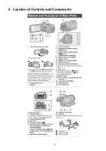
Страница 15: ...15 5 Location of Controls and Components ...
Страница 16: ...16 ...
Страница 17: ...17 ...
Страница 28: ...28 8 3 1 Removal of the Side Case L Unit Fig D1 Fig D2 8 3 2 Removal of the SD OP P C B Fig D3 ...
Страница 29: ...29 8 3 3 Removal of the Cover Board Unit Fig D4 8 3 4 Removal of the ESD P C B HC X900M only Fig D5 ...
Страница 30: ...30 8 3 5 Removal of the Top OP Unit Fig D6 Fig D7 ...
Страница 32: ...32 8 3 9 Removal of the Battery Catcher P C B Fig D11 8 3 10 Removal of the Main P C B Fig D12 ...
Страница 33: ...33 Fig D13 8 3 11 Removal of the Flash P C B Fig D14 ...
Страница 34: ...34 8 3 12 Removal of the Fan Motor Fig D15 8 3 13 Removal of the LCD Case T Unit Fig D16 Fig D17 ...
Страница 35: ...35 Fig D18 8 3 14 Removal of the Monitor P C B Fig D19 Fig D20 8 3 15 Removal of the LCD Panel Unit Fig D21 ...
Страница 36: ...36 Fig D22 8 3 16 Removal of the Front P C B Fig D23 8 3 17 Removal of the Barrier Motor Unit Fig D24 ...
Страница 37: ...37 8 3 18 Removal of the Barrier Case Unit Fig D25 Fig D26 ...
Страница 39: ...39 Fig D30 Fig D31 Fig D32 ...
Страница 40: ...40 8 3 21 Removal of the EVF Lens Holder Unit Fig D33 Fig D34 ...
Страница 41: ...41 8 3 22 Removal of the Top Frame Fig D35 8 3 23 Removal of the Zoom Operation Unit Fig D36 Fig D37 ...
Страница 42: ...42 8 3 24 Removal of the S S Case Unit Fig D38 8 3 25 Removal of the DC Jack P C B Fig D39 Fig D40 ...
Страница 44: ...44 8 3 29 Removal of the MOS Unit Fig D44 8 3 30 Removal of the Stepping Motor Fig D45 ...
Страница 58: ...Model No HC X900MP MPC MPU MEG MEP MEB MGC MEE MGN MGK HC X900EG EF EP EB GC EE GN HC X909EG Parts List Note 6 ...
Страница 63: ...Model No HC X900MP MPC MPU MEG MEP MEB MGC MEE MGN MGK HC X900EG EF EP EB GC EE GN HC X909EG AVIO Main P C B 6 ...
Страница 115: ...Model No HC X900MP MPC MPU MEG MEP MEB MGC MEE MGN MGK HC X900EG EF EP EB GC EE GN HC X909EG EVF Section 6 ...
Страница 116: ...Model No HC X900MP MPC MPU MEG MEP MEB MGC MEE MGN MGK HC X900EG EF EP EB GC EE GN HC X909EG LCD Section 6 ...


