48
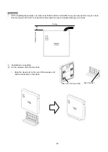
3.3. Installation work of wireless unit
Refer to "1.2 Appearance/Dimensions" for the size of the wireless unit and the mounter.
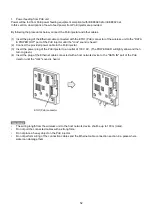
1.
Wall mounting
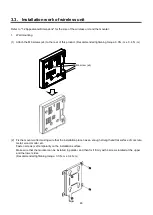
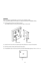
(1) Attach the M6 screws (x4) to the rear of this product. (Recommended tightening torque: 3.0N
・
m ± 0.4 N
・
m)
(2) Fix the mounter after making sure that the installation place has an enough strength and flat surface of concrete,
metal, wood, mortar, etc.
Fasten screws (x2) temporarily on the installation surface.
Make sure that the mounter can be installed in parallel, and then fix it firmly with 4 screws located at the upper
and the lower sides.
(Recommended tightening torque: 3.0 N
・
m ± 0.4 N
・
m)
M6 screw (x4)
Содержание EA-7HW02AP1
Страница 18: ...18 Mounter Outline view Unit mm 24 1 0 84 1 5 4 3 0 5 131 2 5 8 1 0 131 2 5 ...
Страница 19: ...19 Stand Outline view 56 2 1 5 122 2 5 66 9 1 5 ...
Страница 20: ...20 AC adapter Outline view Unit mm 95 9 1 5 28 5 1 0 43 8 1 5 ...
Страница 21: ...21 EA 7HW03AP1 Main unit Outline view Unit mm 38 5 1 5 201 7 2 5 201 7 2 5 ...
Страница 22: ...22 Mounter Outline view Unit mm 26 8 1 0 135 2 5 172 5 2 5 117 5 1 5 6 0 5 11 5 1 0 116 2 1 5 ...
Страница 23: ...23 AC adapter Outline view Unit mm Power cord Outline view 1200 150 50 109 1 5 34 1 5 48 1 5 1000 35 ...
Страница 55: ...55 Chapter 4 Setting method ...
Страница 61: ...61 Chapter 5 Response to error occurrence ...

