25
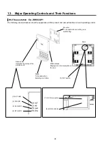
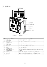
Descriptions about each LED, switch and connector are in the following table.
No.
Signal
Function
(1)
ACT LED
Indicates the operational/error status of the unit.
Lights red
Error detection during operation
Lights green
In operation
(2)
5G LED
Displays the status of wireless IF 5 GHz
Lights green
In normal operation
Off
In the process of start-up
(3)
2.4G LED
Displays the status of wireless IF 2.4 GHz
Lights green
In normal operation
Off
In the process of start-up
(4)
ETH LED
Indicates the link status of the Ethernet port.
Blinks green
In the process of frame transmission/reception
Lights green
Link established
Off
Link disconnected
(5)
INIT switch
(Push switch)
Initializes configuration data and log data.
(6)
Ethernet IF
ETH
(RJ-45 modular jack)
Connect an Ethernet cable.
The ETH port supports power supply from a PoE power feeding equipment.
(7)
DC IN jack
Connect the DC plug of the provided AC adapter.
Содержание EA-7HW02AP1
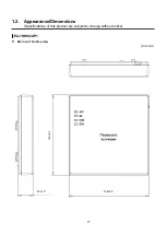
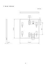
Страница 18: ...18 Mounter Outline view Unit mm 24 1 0 84 1 5 4 3 0 5 131 2 5 8 1 0 131 2 5 ...
Страница 19: ...19 Stand Outline view 56 2 1 5 122 2 5 66 9 1 5 ...
Страница 20: ...20 AC adapter Outline view Unit mm 95 9 1 5 28 5 1 0 43 8 1 5 ...
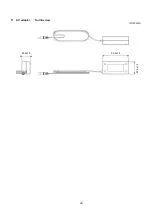
Страница 21: ...21 EA 7HW03AP1 Main unit Outline view Unit mm 38 5 1 5 201 7 2 5 201 7 2 5 ...
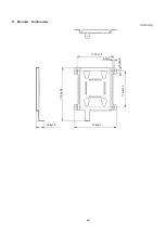
Страница 22: ...22 Mounter Outline view Unit mm 26 8 1 0 135 2 5 172 5 2 5 117 5 1 5 6 0 5 11 5 1 0 116 2 1 5 ...
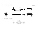
Страница 23: ...23 AC adapter Outline view Unit mm Power cord Outline view 1200 150 50 109 1 5 34 1 5 48 1 5 1000 35 ...
Страница 55: ...55 Chapter 4 Setting method ...
Страница 61: ...61 Chapter 5 Response to error occurrence ...


