28
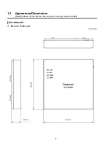
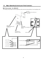
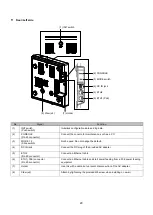
Front
No.
Signal
Function
(1)
ACT LED
Indicates the operational/error status of the unit.
Lights green
In operation
Blinks green
In the process of start-up
Blinks red
In the process of upgrade
Lights red
Error detection during operation
(2)
2.4G LED
Displays the status of wireless IF 2.4 GHz
Lights green
In normal operation
Off
In the process of start-up
(3)
5G LED
Displays the status of wireless IF 5 GHz
Lights green
In normal operation
Off
In the process of start-up
(4)
ETH1 LED
Indicates the link status of the Ethernet port.
Blinks green
In the process of frame transmission/reception
Lights green
Link established
Off
Link disconnected
(5)
ETH2 LED
Indicates the link status of the Ethernet port.
Blinks green
In the process of frame transmission/reception
Lights green
Link established
Off
Link disconnected
(1) ACT LED
(2) 2.4G LED
(3) 5G LED
(4) ETH1 LED
(5) ETH2 LED
Содержание EA-7HW02AP1
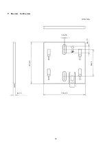
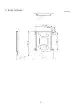
Страница 18: ...18 Mounter Outline view Unit mm 24 1 0 84 1 5 4 3 0 5 131 2 5 8 1 0 131 2 5 ...
Страница 19: ...19 Stand Outline view 56 2 1 5 122 2 5 66 9 1 5 ...
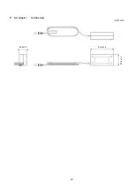
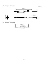
Страница 20: ...20 AC adapter Outline view Unit mm 95 9 1 5 28 5 1 0 43 8 1 5 ...
Страница 21: ...21 EA 7HW03AP1 Main unit Outline view Unit mm 38 5 1 5 201 7 2 5 201 7 2 5 ...
Страница 22: ...22 Mounter Outline view Unit mm 26 8 1 0 135 2 5 172 5 2 5 117 5 1 5 6 0 5 11 5 1 0 116 2 1 5 ...
Страница 23: ...23 AC adapter Outline view Unit mm Power cord Outline view 1200 150 50 109 1 5 34 1 5 48 1 5 1000 35 ...
Страница 55: ...55 Chapter 4 Setting method ...
Страница 61: ...61 Chapter 5 Response to error occurrence ...


