37
9.4.4.
Removal of the 2nd Lens Frame
Unit
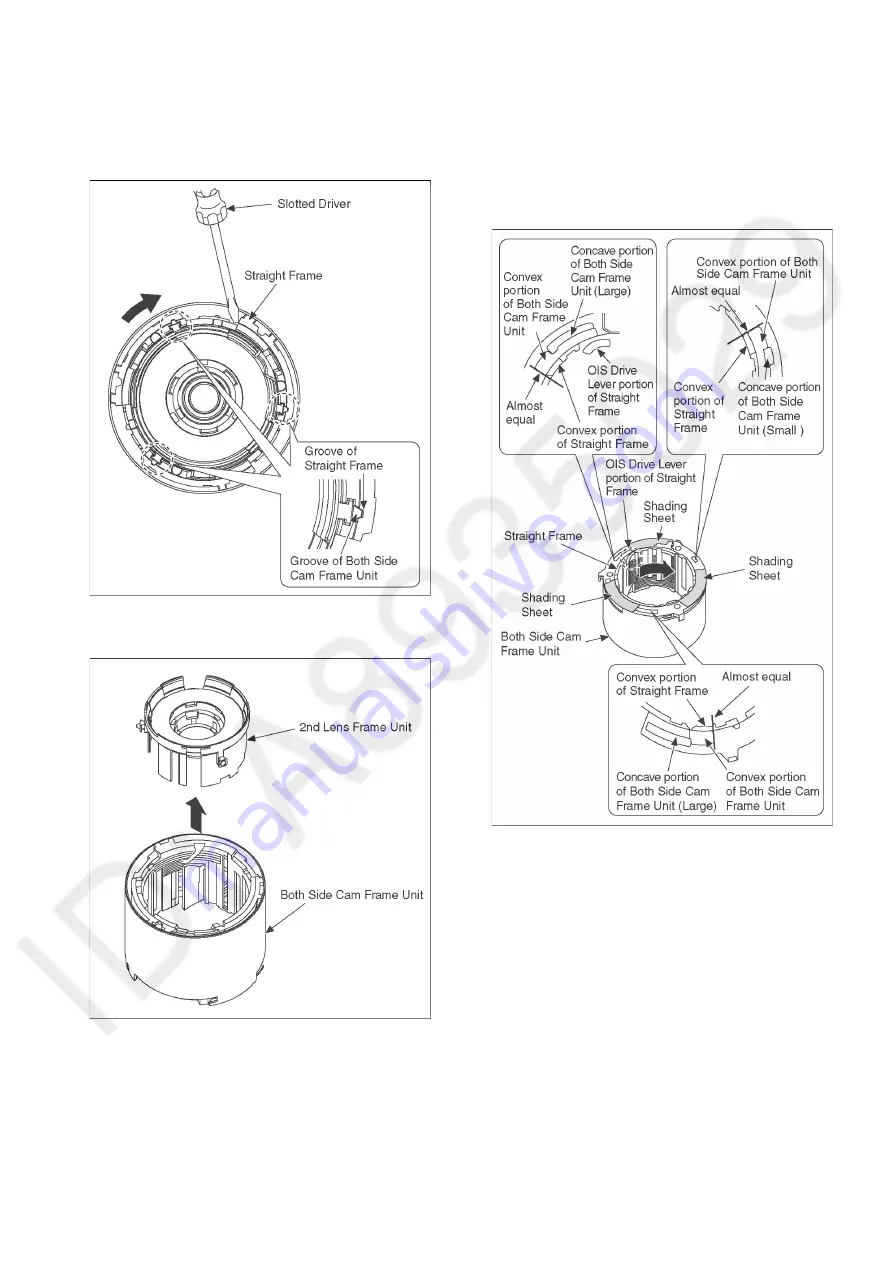
1. Turn the Straight Frame using Slotted Driver, etc. and
then align the Groove of Straight Frame and Groove of
Both Side Cam Frame Unit.
2. Remove the 2nd Lens Frame Unit from the Both Side
Cam Frame Unit.
9.5.
Assembly Procedure for Lens
9.5.1.
Insert the 2nd Lens Frame Unit
1. Turn the Straight Frame in the direction of arrow, then
align the convex portion of Straight Frame and the
concave portion of Both Side Cam Frame Unit.
* Refer to the OIS Drive Lever portion of Straight Frame
as shown below.
Содержание DMC-TZ80EB
Страница 17: ...17 ...
Страница 27: ...27 9 3 1 Removal of the Rear Case Unit Fig D1 ...
Страница 28: ...28 9 3 2 Removal of the Rear Operation P C B Unit Fig D2 9 3 3 Removal of the LCD Unit Fig D3 ...
Страница 29: ...29 Fig D4 9 3 4 Removal of the Main P C B Speaker Fig D5 ...
Страница 30: ...30 Fig D6 Fig D7 9 3 5 Removal of the Eye Sensor FPC Fig D8 ...
Страница 31: ...31 9 3 6 Removal of the Lens Unit Fig D9 9 3 7 Removal of the Top Case Unit Fig D10 ...
Страница 32: ...32 9 3 8 Removal of the LVF Unit Top P C B Unit Flash Unit Fig D11 Fig D12 ...
Страница 47: ...47 ...
Страница 48: ...48 ...
Страница 49: ...49 ...
Страница 60: ...60 ...


