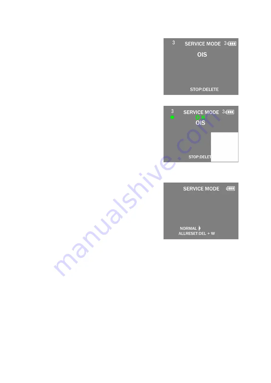
background image

31

9.3.1.3.

Execute Adjustment
(In case of “OIS Adjustment”)

1. Perform step “9.3.1.1.” to “9.3.1.2.”, to reset the OIS flag

status “F” (Set) to “0” (Reset)

2. Press “[ W ] side of the Zoom button” after Flag reset.

OIS Adjustment screen is displayed on the LCD panel.
(Refer to Fig.3-3)

3. Press the [ Shutter ] button. 

The adjustment will start  automatically.

4. When the adjustment is completed successfully, adjust-

ment report menu appears with Green OK on the LCD
monitor. (Refer to Fig.3-4)

Fig.3-3

Fig.3-4

9.3.1.4.

Attention point during Adjustment

1. Step “9.3.1.3.” procedure shows OIS adjustment as an

example. To perform the adjustment, refer to the “9.3.2.
Adjustment Specifications” table which shows key point
for each adjustment.

2. Do not move the light box, the camera or the chart while

adjusting. If one of these is moved accidentally, start the
adjustment again.

3. Do not press any buttons/keys until the default menu

(Refer to Fig.3-5) is displayed on the LCD monitor. Other-
wise, adjustment data may not be stored properly.

4. If the adjustment is interrupted accidentally, the alignment

data may not be properly saved in the Flash-ROM.

Fig.3-5

9.3.1.5.

Finalizing the Adjustment

1. Several adjustment flags can be reset (“F” into “0”) at the same time. In this case, when the adjustment has been completed,

the screen will change showing the adjustment for the next item until all reset items are completed. 
Also, when the [ Shutter ] button is pressed, the screen jump to the next adjustment item.

2. To cancel the adjustment mode while in the process of performing the adjustment, follow this procedures.
3. Operate the following, when escaping the Electrical Adjustment mode on the way.

(1) Press “[ Delete/Cancel ] button”.
(2) Press “[ RIGHT ] of Cursor button”.

NOTE:

• If adjustment is cancelled with above procedure, adjustment is not completed. Make sure to adjust it later.
• Adjustment software “DIAS” is able to control the status of the adjustment flags.

Содержание DMC-FH10P

Страница 1: ... DMC FH10P DMC FH10PC DMC FH10PU DMC FH10GA DMC FH10GC DMC FH10GF DMC FH10GK DMC FH10GN DMC FH10GT DMC FS50EB DMC FS50EE DMC FS50EF DMC FS50EG DMC FS50EP Colour DMC FH10 S Silver Type except P PC K Black Type P Pink Type except PC GN V Violet Type except P PC GT DMC FS50 S Silver Type K Black Type P Pink Type only EE V Violet Type only EE ...

Страница 2: ... 5 Location of Controls and Components 13 6 Service Mode 15 6 1 Error Code Memory Function 15 7 Service Fixture Tools 18 7 1 Service Fixture and Tools 18 7 2 When Replacing the Main P C B 18 7 3 Service Position 19 8 Disassembly and Assembly Instructions 20 8 1 Disassembly Flow Chart 20 8 2 P C B Location 20 8 3 Disassembly Procedure 21 8 4 Removal of the CCD FPC Unit 27 9 Measurements and Adjustm...

Страница 3: ...exposed to shock hazards 1 2 Leakage Current Cold Check 1 Unplug the AC cord and connect a jumper between the two prongs on the plug 2 Measure the resistance value with an ohmmeter between the jumpered AC plug and each exposed metal lic cabinet part on the equipment such as screwheads connectors control shafts etc When the exposed metal lic part has a return path to the chassis the reading should ...

Страница 4: ...cuit on Flash Top P C B when servicing Discharging Procedure 1 Put the insulation tube on the lead part of resistor ERG5SJ102 1kΩ 5W An equivalent type of resistor may be used 2 Put the resistor between both terminals of E Capacitor on the Flash Top P C B for approx 5 seconds 3 After discharging confirm that the E Capacitor voltage is lower than 10V by using a voltmeter Fig F1 ...

Страница 5: ...ices 4 Use only an antistatic solder removal device Some solder removal devices not classified as antistatic ESD protected can generate electrical charge sufficient to damage ES devices 5 Do not use freon propelled chemicals These can generate electrical charges sufficient to damage ES devices 6 Do not remove a replacement ES device from its protective package until immediately before you are read...

Страница 6: ...tment must be performed About the Optical tilt adjustment refer to the 9 3 2 Adjustment Specifications for details 3 2 2 P C B In order to remove Main P C B it is necessary to remove the solder 3 points of the battery terminal It is judged that the analysis of the Main P C B which the battery terminal separated is difficult So the Main P C B is unit exchange Please fix individually about the Flash...

Страница 7: ...t for which the lead free solder is used Definition The letter of PbF is printed on the P C B using the lead free solder To put lead free solder it should be well molten and mixed with the original lead free solder Remove the remaining lead free solder on the P C B cleanly for soldering of the new IC Since the melting point of the lead free solder is higher than that of the normal lead solder it t...

Страница 8: ...E e DMC FH10GT f DMC FH10GN g DMC FH10PU GA GC GF GK What is the difference is that the INITIAL SETTINGS data which is stored in Flash ROM mounted on Main P C B 3 4 1 Defining methods To define the model suffix to be serviced refer to the nameplate which is putted on the bottom side of the Unit NOTE After replacing the Main P C B be sure to achieve adjustment The service software is available at T...

Страница 9: ...ard 1 Turn the Power on 2 Press the MODE button and select the NORMAL PICTURE mode by Cursor buttons then press the MENU SET button 3 Turn the Power off If the unit is other than NORMAL PICTURE mode it does not display the initial settings menu Step 1 The temporary cancellation of INITIAL SETTINGS Press the PLAYBACK button UP of Cursor button and W side of Zoom button simultaneously turn the Power...

Страница 10: ... been replaced all of the model suffix is displayed as follows Five pages in total CASE 2 Other than After replacing Main P C B Step 5 Choose the model suffix in INITIAL SETTINGS Refer to CAUTION 1 Caution After replacing Main P C B The model suffix can been chosen JUST ONE TIME Once one of the model suffix have been chosen the model suffix lists will not be displayed thus it can not be changed Th...

Страница 11: ...s shown in the following table Default setting After INITIAL SETTINGS MODEL VIDEO OUTPUT LANGUAGE DATE REMARKS a DMC FH10 Japan domestic model NTSC Japanese Year Month Date b DMC FH10P NTSC English Month Date Year c DMC FH10PC NTSC English Month Date Year d DMC FH10PU NTSC Spanish Month Date Year e DMC FH10GA PAL English Date Month Year f DMC FH10GC PAL English Date Month Year g DMC FH10GF PAL Eng...

Страница 12: ...12 4 Specifications The following specification is for DMC XS1P DMC FH10P Some specifications may differ depending on model suffix ...

Страница 13: ...13 5 Location of Controls and Components The following description is for DMC FH10P Some descriptions may differ depending on model suffix ...

Страница 14: ...14 ...

Страница 15: ... can be performed without inserting memory card 1 Turn the Power on 2 Press the MODE button and select the NORMAL PICTURE mode by Cursor buttons then press the MENU SET button 3 Turn the Power off If the unit is other than NORMAL PICTURE mode it does not display the initial settings menu Step 1 The temporary cancellation of INITIAL SETTINGS Press the PLAYBACK button UP of Cursor button and W side ...

Страница 16: ...16 Error Code List The error code consists of 8 bits data and it shows the following information ...

Страница 17: ...this error occurred under the condition of INITIAL SETTINGS has been released Example Factory assembling line before unit shipment Service mode etc It means that this error is occurred at service side 2 About indication 18 0 0 01 to 18 0 0 60 The third digit from the right shows one of the hexadecimal 0 to F character Step 3 How to exit from Error Code display mode Simply turn the power off Since ...

Страница 18: ...ture and Tools The following Service Fixture and tools are used for checking and servicing this unit 7 2 When Replacing the Main P C B After replacing the Main P C B be sure to achieve adjustment The service software is available at TSN Website ...

Страница 19: ... discharge the E Capacitor on Flash Top P C B Refer to How to Discharge the E Capacitor on Flash Top P C B The E Capacitor voltage is not lowered soon even if the AC Cord is unplugged or the battery is removed 2 Be careful of the high voltage circuit on Flash Top P C B 3 DO NOT allow other parts to touch the high voltage circuit on Flash Top P C B ...

Страница 20: ...20 8 Disassembly and Assembly Instructions 8 1 Disassembly Flow Chart This is a disassembling chart When assembling perform this chart conversely 8 2 P C B Location ...

Страница 21: ... Convexes Connector B LCD Unit 4 Lens Unit W CCD Fig D5 1 Screw D 1 Screw E 3 Locking tabs 2 Convexes Frame Plate Connector C Connector D Lens Unit W CCD 5 Front Case Unit Fig D6 Front Case Unit Fig D7 Discharge the E Capacitor 6 Flash Top P C B Fig D8 Connector E Fig D9 1 Screw F 1 Locking tab 2 Convexes Flash Top P C B 7 Main P C B Speaker Fig D10 Terminal Cover 3 Solders 1 Screw G 1 Convex Main...

Страница 22: ...22 Fig D2 8 3 2 Removal of the Rear Op Plate Unit Fig D3 ...

Страница 23: ...23 8 3 3 Removal of the LCD Unit Fig D4 8 3 4 Removal of the Lens Unit W CCD Fig D5 ...

Страница 24: ...24 8 3 5 Removal of the Front Case Unit Fig D6 Fig D7 ...

Страница 25: ...25 8 3 6 Removal of the Flash Top P C B Fig D8 Fig D9 ...

Страница 26: ... eliminate the gap between Main P C B and Frame Unit Otherwise soldered terminal A part may be damaged after assembling 8 3 8 Removal of the Battery Door Unit Fig D11 NOTE When Installing Make sure to confirm the following points when installing The Screw is tightened enough Installing conditions are fine No distortion no abnormal space No dust and or dirt on Lens surfaces LCD image is fine No dus...

Страница 27: ...s ened even a little the optical tilt adjustment is required When loosen the screw H necessary the optical tilt adjust ment at the end of assembling Refer to item 9 3 2 To prevent the CCD FPC unit from catching the dust and dirt do not remove the CCD FPC unit except for replacing Fig D12 ...

Страница 28: ... 9 2 Before Disassembling the unit 9 2 1 Initial Setting Release The cameras specification are initially set in accordance with model suffix such as EB EG GK GC and so on Unless the initial setting is not released an automatic alignment software in the camera is not able to be executed when the align ment is carried out Note The initial setting should be again done after completing the alignment O...

Страница 29: ... Method of Non PC backup 1 Insert the memory card into the camera 2 Set the camera to Temporary cancellation of the initial settings 3 Select the SETUP menu From the SETUP menu select ROM_BACKUP NOTE This item is not listed on the customer s SETUP menu 4 When this ROM_BACKUP item is selected the following submenus are displayed Fig 2 1 DSC Integrated Assist Software Method of Using PC Same as TATS...

Страница 30: ...displays SERVICE MODE Refer to Fig 3 1 Fig 3 1 9 3 1 2 Status Adjustment Flag Setting Reset Not yet adjusted the status flag condition 1 After pressing the W side of Zoom button the LCD monitor displays the Flag status screen Refer to Fig 3 2 2 Select item by pressing the Cursor buttons Gray cursor is moved accordingly 3 Press the Delete Cancel button NOTE The selected item s flag has been changed...

Страница 31: ...ress any buttons keys until the default menu Refer to Fig 3 5 is displayed on the LCD monitor Other wise adjustment data may not be stored properly 4 If the adjustment is interrupted accidentally the alignment data may not be properly saved in the Flash ROM Fig 3 5 9 3 1 5 Finalizing the Adjustment 1 Several adjustment flags can be reset F into 0 at the same time In this case when the adjustment h...

Страница 32: ...x table shows the relation between the replaced part and the Necessary Adjustment When a part is replaced make sure to perform the necessary adjustment s in the order indicated The table below shows all the information necessary to perform each adjustment ...

Страница 33: ...33 ...

Страница 34: ...escribed in 3 4 2 INITIAL SETTINGS for details IMPORTANT 1 The initial setting should be done again after completing the alignment Otherwise the camera will not work properly Therefore as a warning the camera display a warning symbol on the LCD monitor every time the camera is turned off 2 Confirm that status of all adjustment flag show F Even if one of the adjustment flag shows 0 initial setting ...

Страница 35: ...LCD Panel with your hand When cleaning the lens use air Blower to blow off the dust When cleaning the LCD Panel dampen the lens cleaning paper with lens cleaner and the gently wipe the its surface Note The Lens Cleaning KIT VFK1900BK Only supplied as 10 set Box is available as Service Aid ...

Страница 36: ... FLASH TOP OPERATION UNIT SHUTTER ZOOM OIS CONTROL LENS DRIVE LCD DRIVE MICROPHONE AMP SPEAKER CONTROL VIDEO OUT 25mm 125mm GYRO SENSOR AMP MICROPHONE SPEAKER CDS AGC A D TG CCD DRIVER 12MHz 32 768MHz IC8001 IGBT DRIVER LENS DRIVER DMC FH10 FS50 OVERALL BLOCK DIAGRAM COLOR LCD PANEL 2 7 PANEL 230k dots MAIN P C B CCD 1 2 33 16 1 MEGA PIX IC7101 POWER SUPPLY BATTERY POWER AV OUT DIGITAL TERMINAL BA...

Страница 37: ...8101 SHUTTER SW D8101 AF ASSIST LED SHUTTER 0 SHUTTER 1 AF CATHODE B6301 Timer Back UP BATTERY RTC BAT M5001 MICROPHONE MIC P MIC N CL8001 CL8002 CL8007 D GND ET8003 SLEEVE GND POWER SW 2 1 4 3 S8102 POWER FP8001 17 FP8001 4 FP8001 3 FP8001 5 FP8001 6 FP8001 7 FP8001 15 FP8001 13 FP8001 16 FP8001 18 21 FP8001 8 11 FP8001 14 FP8001 12 CPWR FP8001 1 DMC FH10 FS50 SUB OPERATION BLOCK DIAGRAM SUB OPER...

Страница 38: ...O YHO YHO GND FMAP FMBP FMAN ZM ZM ZENC LED FZHP VCC FZHP ABS YDR SH SH IRIS IRIS XDR XHI XHI YHI YHI FMBN FMAP FMBP FMAN ZM ZM ZENC ABS FZHP LED 1 3 5 7 9 11 13 15 17 19 21 23 25 27 29 31 33 35 37 2 4 6 8 10 12 14 16 18 20 22 24 26 28 30 32 34 36 FP9003 VCOM CS SCL VSYNC D7 D5 D3 D1 GND LCD DET1 DVDD V2 V4 V5 VDD3 V7 VGH AGND COMDC VCOM VLED GRB SDA HSYNC DCLK D6 D4 D2 D0 LCD DE0 VDDIO V1 V3 VDD2...

Отзывы: