
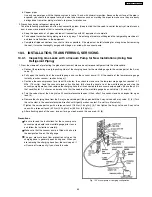


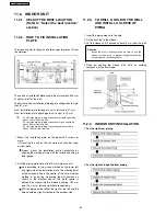


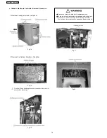


11.3.5. CONNECT THE CABLE TO THE
OUTDOOR UNIT
1. Remove the control board cover from the unit by loosening
the screw.
2. Connecting cable between indoor unit and outdoor unit
shall be approved polychloroprene sheathed 4 (E9CK,
E12CK, E15CK) × 1.5 mm
2
flexible cord, type designation
245 IEC 57 or heavier cord.
3. Secure the cable onto the control board with the holder
(clamper).
4. Attach the control board cover back to the original position
with the screw.
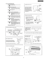
11.3.6. PIPE INSULATION
1. Please carry out insulation at pipe connection portion as
mentioned in Indoor/Outdoor Unit Installation Diagram.
Please wrap the insulated piping end to prevent water from
going inside the piping.
2. If drain hose or connecting piping is in the room (where dew
may form), please increase the insulation by using POLY-E
FOAM with thickness 6 mm or above.
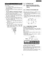
DISPOSAL OF OUTDOOR UNIT DRAIN WATER
•
If a drain elbow is used, the unit should be placed on a
stand which is taller than 3 cm.
•
If the unit is used in an area where temperature falls below
0°C for 2 or 3 days in succession, it is recommended not to
use a drain elbow, for the drain water freezes and the fan
will not rotate.
CHECK THE DRAINAGE
•
Open front panel and remove air filters.
(Drainage checking can be carried out without removing the
front grille.)
•
Pour a glass of water into the drain tray-styrofoam.
•
Ensure that water flows out from drain hose of the indoor
unit.
EVALUATION OF THE PERFORMANCE
•
Operate the unit at cooling operation mode for fifteen
minutes or more.
•
Measure the temperature of the intake and discharge air.
•
Ensure the difference between the intake temperature and
the discharge is more than 8°C.
CHECK ITEMS
Is there any gas leakage at flare nut connections?
Has the heat insulation been carried out at flare nut
connection?
Is the connecting cable being fixed to terminal board firmly?
Is the connecting cable being clamped firmly?
Is the drainage OK?
(Refer to “Check the drainage” section)
Is the earth wire connection properly done?
Is the indoor unit properly hooked to the installation plate?
Is the power supply voltage complied with rated value?
Is there any abnormal sound?
Is the cooling operation normal?
Is the thermostat operation normal?
Is the remote control’s LCD operation normal?
Is the air purifying filter installed?
65
CS-E15CKP CU-E15CKP5
Содержание CS-E15CKP
Страница 8: ...4 Dimensions 8 CS E15CKP CU E15CKP5 ...
Страница 9: ...9 CS E15CKP CU E15CKP5 ...
Страница 10: ...5 Refrigeration Cycle Diagram 10 CS E15CKP CU E15CKP5 ...
Страница 11: ...6 Block Diagram 11 CS E15CKP CU E15CKP5 ...
Страница 12: ...7 Wiring Diagram 12 CS E15CKP CU E15CKP5 ...
Страница 39: ...IONIZE 42 43 44 41 39 CS E15CKP CU E15CKP5 ...
Страница 40: ...IONIZER IONIZER IONIZER IONIZER 40 CS E15CKP CU E15CKP5 ...
Страница 41: ...CZ SFD72P 41 CS E15CKP CU E15CKP5 ...
Страница 42: ...42 CS E15CKP CU E15CKP5 ...
Страница 43: ... H23 H27 H28 43 CS E15CKP CU E15CKP5 ...
Страница 44: ...44 CS E15CKP CU E15CKP5 ...
Страница 45: ...45 CS E15CKP CU E15CKP5 ...
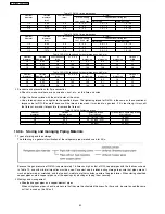
Страница 75: ...13 Technical Data 75 CS E15CKP CU E15CKP5 ...
Страница 87: ...87 CS E15CKP CU E15CKP5 ...
Страница 88: ...How to use electronic circuit diagram 88 CS E15CKP CU E15CKP5 ...
Страница 89: ...18 1 REMOTE CONTROL 89 CS E15CKP CU E15CKP5 ...
Страница 90: ...18 2 PRINT PATTERN INDOOR UNIT PRINTED CIRCUIT BOARD 90 CS E15CKP CU E15CKP5 ...
Страница 91: ...18 3 PRINT PATTERN OUTDOOR UNIT PRINTED CIRCUIT BOARD VIEW 91 CS E15CKP CU E15CKP5 ...
Страница 92: ...92 CS E15CKP CU E15CKP5 ...
Страница 93: ...93 CS E15CKP CU E15CKP5 MAICO Printed in Malaysia ...
Страница 94: ......


