


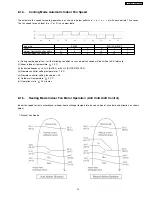


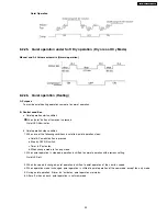


8.2.18. Indoor Heat Exchanger Temperature Control
This control is applicable for Heating Mode operation only.
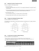
The compressor operating frequency is regulated in accordance to indoor heat exchanger temperature as shown in below figures.
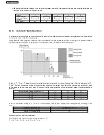
8.2.19. Intake Air Temperature Control
This control is applicable for Heating Mode operation only.
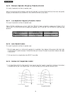
Compressor will operate at maximum of 56 Hz or 68.5 Hz for E9CKP and E12CKP/E15CKP respectively if either one of the below
conditions occur:
1. When the intake air temperature is 10°C or above and remote controller setting fan speed is Lo or lower.
2. When the intake air temperature is 30°C or above.
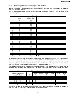
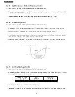
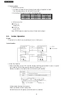
8.2.20. Deice Operation Control
This control is applicable for Heating Mode operation only.
Deice operation occurs when the deice operation starting signal is generated. This happens when one of he following condition
occurs. However, the first deice operation will begin one hour after the start of heating mode operation.
Condition
Outdoor heat exchanger
temp. T
h
< 3°C
In between, for 3 minutes,
outdoor heat exchanger
temp. T
h
Provided, compressor is
ON and outdoor air temp.
T
o
1
For 120 minutes
< -6°C
> -1°C
2
For 80 minutes
< -7°C
> -1°C
3
For 40 minutes
< -9°C
-3°C
4
For 40 minutes
< -11°C
> -3°C
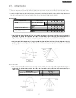
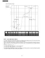
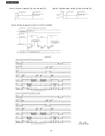
Once the deice operation signal produced, the instructed frequency for the operation of compressor will be set to zero hertz (0 Hz)
for 30 seconds. Then, deice operation starts with both indoor and outdoor fan motor, and 4-way valve turn off for 30 seconds. The
compressor operates following the frequency as shown in below chart that depending on outdoor heat exchanger temperature and
operation period, with a maximum of 10 minutes and 30 seconds. When the deice operation ends, before back to normal operation,
the instructed frequency for compressor will be set to zero hertz (0 Hz) again and outdoor fan motor will turn on for a period of 59
seconds.
29
CS-E15CKP CU-E15CKP5
Содержание CS-E15CKP
Страница 8: ...4 Dimensions 8 CS E15CKP CU E15CKP5 ...
Страница 9: ...9 CS E15CKP CU E15CKP5 ...
Страница 10: ...5 Refrigeration Cycle Diagram 10 CS E15CKP CU E15CKP5 ...
Страница 11: ...6 Block Diagram 11 CS E15CKP CU E15CKP5 ...
Страница 12: ...7 Wiring Diagram 12 CS E15CKP CU E15CKP5 ...
Страница 39: ...IONIZE 42 43 44 41 39 CS E15CKP CU E15CKP5 ...
Страница 40: ...IONIZER IONIZER IONIZER IONIZER 40 CS E15CKP CU E15CKP5 ...
Страница 41: ...CZ SFD72P 41 CS E15CKP CU E15CKP5 ...
Страница 42: ...42 CS E15CKP CU E15CKP5 ...
Страница 43: ... H23 H27 H28 43 CS E15CKP CU E15CKP5 ...
Страница 44: ...44 CS E15CKP CU E15CKP5 ...
Страница 45: ...45 CS E15CKP CU E15CKP5 ...
Страница 75: ...13 Technical Data 75 CS E15CKP CU E15CKP5 ...
Страница 87: ...87 CS E15CKP CU E15CKP5 ...
Страница 88: ...How to use electronic circuit diagram 88 CS E15CKP CU E15CKP5 ...
Страница 89: ...18 1 REMOTE CONTROL 89 CS E15CKP CU E15CKP5 ...
Страница 90: ...18 2 PRINT PATTERN INDOOR UNIT PRINTED CIRCUIT BOARD 90 CS E15CKP CU E15CKP5 ...
Страница 91: ...18 3 PRINT PATTERN OUTDOOR UNIT PRINTED CIRCUIT BOARD VIEW 91 CS E15CKP CU E15CKP5 ...
Страница 92: ...92 CS E15CKP CU E15CKP5 ...
Страница 93: ...93 CS E15CKP CU E15CKP5 MAICO Printed in Malaysia ...
Страница 94: ......


