background image

10.4.2.

 Transferring (Using New Refrigerant Piping)

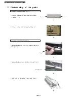
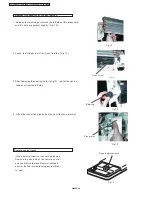
 1. Removing the unit

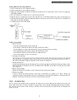
 a. Collecting the refrigerant into the outdoor unit by pumping down

The refrigerant can be collected into the outdoor unit (pumping down) by pressing the TEST RUN button, even when the
temperature of the room is low.

ıı ı

ı

ˇı

ˇ ı

ˇ ı

ˇ ıCheck to make sure that the valve stems of the 2-way valve and 3-way valve have been opened by turning them counter-

clockwise. (Remove the valve stem caps and check to see that the valve stems are fully opened position. Always use
a hex wrench (with 4-mm opposing sides) to operate the valve stems.)

ıı ı

ı

ˇı

ˇ ı

ˇ ı

ˇ ıPress the TEST RUN button on the indoor unit, and allow preliminary for 5-6 minutes. (TEST RUN mode)

ıı ı

ı

ˇı

ˇ ı

ˇ ı

ˇ ıAfter stopping the operation, let the unit sit for about 3 minutes, then close the 2-way valve by turning the valve stem in

the clockwise direction.

ıı ı

ı

ˇı

ˇ ı

ˇ ı

ˇ ıPress the TEST RUN button on the indoor unit again, and after 2-3 minutes of operation, turn the valve stem of the 3-

way valve quickly in the clockwise direction to close it, then stop the operation.

ıı ı

ı

ˇı

ˇ ı

ˇ ı

ˇ ıTighten the caps of the 2-way valve and 3-way valve to the stipulated torque.

ıı ı

ı

ˇı

ˇ ı

ˇ ı

ˇ ıRemove the connection pipes (liquid side and gas side).

 2. Installing the unit

Install the unit using new refrigerant piping. Follow the instructions in section 4.1 to evacuate the pipes connecting the indoor
and outdoor units, and the pipes of the indoor unit, and check for gas leaks.

10.4.3.

 AC Units Replacement (Using Existing Refrigerant Piping)

When replacing and R410A AC unit with another R410A AC unit, you should re-flare the refrigerant piping. Even though the
replacement AC unit uses the R410A, problems occur when, for example, either the AC unit maker or the refrigerating machine oil
is different.
When replacing an R22 AC unit with an R410A AC unit, the following checks and cleaning procedures are necessary but are
difficult to do because of the chemical characteristics of the refrigerating machine oil (as described in items c) and d) of section
10.1.1.(2)). In this case, you should use new refrigerant piping rather than the existing piping.
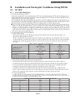
 1. Piping check

Because of the different pressure characteristics of R22 and R410A, the design pressure for the equipment is 1.6 times
different. the wall thickness of the piping must comply with that shown in Table 10, but this is not easy to check. Also, even if
the thickness is correct, there may be flattened or bent portions midway through the piping due to sharp curves. Buried sections
of the piping also cannot be checked.

 2. Pipe cleaning

A large quantity of refrigerating machine oil (mineral oil) adheres to existing pipes due to the refrigeration cycle circulation. If the
pipes are used just as they are for the R410A cycle, the capacity will be lowered due to the incompatibility of this oil with the
R410A, or irregularities may occur in the refrigeration cycle. For this reason, the piping must be thoroughly cleaned, but this is
difficult with the present technology.

10.4.4.

 Refrigerant Compatibility (Using R410A Refrigerant in R22 ACs and Vice Versa)

Do not operate an existing R22 AC with the new R410A refrigerant. Doing so would result in improper functioning of the equipment
or malfunction, and might lead to a major accident such as an explosion in the refrigeration cycle. Similarly, do not operate an
R410A AC with R22 refrigerant. The chemical reaction between the refrigerating machine oil used in R410A ACs and the chlorine
that is contained in R22 would cause the refrigerating machine oil to degrade and lead to malfunction.

10.4.5.

 Recharging Refrigerant During Servicing

When recharging is necessary, insert the specified amount of new refrigerant in accordance with the following procedure.

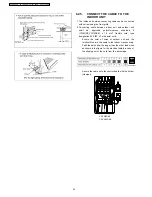
 1. Connect the charging hose to the service port of the outdoor unit.

 2. Connect the charging hose to the vacuum pump adaptor. At this time, fully open the 2-way valve and 3-way valve.

 3. Fully open the handle Lo of the manifold gauge, turn on the power of the vacuum pump and continue the vacuum process for

at least one hour.

 4. Confirm that the low pressure gauge shows a reading of -0.1 Mpa (-76 cmHg), then fully close the handle Lo, and turn off the

vacuum pump. Wait for 1-2 minutes, then check to make sure that the needle of the Low pressure gauge has not returned. See
Fig. 13 for the remaining steps of this procedure.

47

CS-YW9DKE / CU-YW9DKE / CS-YW12DKE / CU-YW12DKE

Содержание CS/CU-YW9DKE

Страница 1: ...sult in serious injury or death 1 Features 2 2 Functions 3 3 Product Specifications 6 4 Dimensions 11 5 Refrigeration Cycle Diagram 12 6 Block Diagram 13 7 Wiring Diagram 14 8 Operation Details 15 9 I...

Страница 2: ...n to reduce dust and smoke Auto Restart Control Automatically restart after power failure CS YW9DKE CU YW9DKE CS YW12DKE CU YW12DKE Enviromental Friendly For Refrigerant R410A Model 12 hour Timer Sett...

Страница 3: ...ure Setting 16 to 30 Auto Operation Timer Operation Selection Stop Start Operation Control set the ON OFF Timer hourly later Set Cancel Timer Operation Set timer Cancel the set timer 2 Functions Remot...

Страница 4: ...ressing this button for 15seconds to start or end the Demonstration Mode Auto Switch Button Air quality Green Orange Red Anti freezing Control for the Evaporator Cooling or Soft Dry Operation Warm Boo...

Страница 5: ...r 60 seconds It stops immediately with remote control ON OFF button Anti freezing operation for outdoor unit during Heating Mode Operation only Temperature of the condenser is tested by TRS Deicing Co...

Страница 6: ...e Motor type Fan Speed Low Med High Rated Output Input Inch Inch Inch Inch mm m mm mm mm kg W W W rpm rpm rpm CS YW9DKE CU YW9DKE 2 65 2 95 1 6 Single 230 50 SIDE VIEW TOP VIEW 7 34 8 5 9 6 Cooling hi...

Страница 7: ...F V F V Evaporator Copper Slot type Plate fin configuration forced draft 2 x 12 2X24 Condenser Copper Corrugation type 21 610x252x25 4 Electronic Control P P Honeycomb 17 Capillary Tube 870 O L P 230...

Страница 8: ...h Height Width Depth Type Motor Type Rated output type Motor type Fan Speed Low Med High Rated Output Input Inch Inch Inch Inch mm m mm mm mm kg W W W rpm rpm rpm CS YW12DKE CU YW12DKE 3 10 3 60 1 9 S...

Страница 9: ...rculation Inner Diameter mm c c g mm L min mm F V F V Evaporator Copper Slot type Plate fin configuration forced draft 2 x 12 2X24 Condenser Copper Corrugation type 21 610x252x25 4 Electronic Control...

Страница 10: ...nd the installation plate Front View Drain Port 770 Air intake 250 49 61 5 Side view 205 Air outlet Left Piping Hole Right Piping Hole 79 OFF MODE TEMP OFF ON ON CANCEL SET STD TIMER FANSPEED AIRSWING...

Страница 11: ...650 61 6 10cm 100cm Required space for installation Front View Side View Top View Unit mm 123 8 62 2 61 6 88 88 650 668 250 230 530 55 8 293 Air intake Air outlet CU YW12DKE 10cm 11 CS YW9DKE CU YW9DK...

Страница 12: ...CS CU YW9DKE CS CU YW12DKE 5 Refrigeration Cycle Diagram INTAKE AIR SENSOR PIPING SENSOR 4 way valve PIPING SENSOR AIR QUALITY SENSOR Cooling Heating 12 CS YW9DKE CU YW9DKE CS YW12DKE CU YW12DKE...

Страница 13: ...CR201 3 4 1 RY HOT SSR202 SSR201 FUSE RY PWR OUTDOOR UNIT Receiver Remote Control F M 4 Valve Compressor Sensor Indicator Piping Sensor O L P INDOOR UNIT 13 POWER SUPPLY AC230V 50Hz CS YW12DKE CU YW12...

Страница 14: ...IPING TEMP SENSOR INTAKE TEMP INDOOR UNIT POWER SUPPLY CORD POWER SUPPLY CORD AC 230 50Hz AC 230 50Hz STEPPING MOTOR OUTDOOR UNIT TERMINAL BOARD 1 L 2 N 3 4 1 L 2 N 3 4 OUTDOOR UNIT OUTDOOR FAN MOTOR...

Страница 15: ...i Freezing Control If temperature of evaporator is lower than 2 continuously for 4 minutes the compressor will cease to prevent the evaporator from freezing Fan speed setting will not be changed When...

Страница 16: ...perature reaches the set temp on remote control and then Soft Dry will be activated During Soft Dry Mode the fan of indoor unit will operate at super low speed The soft dry mode will run for less than...

Страница 17: ...omp Indoor Fan Outdoor Fan Operation Indicator 6 6 6 1 6 1 1 4 Operation status Time Operate Stop Super Low Super Low Super Low Super Low Low 1 5 Cooling mode operation activated Intake Air temp 1 0 C...

Страница 18: ...eration with the speed at super low Compressor Stops Compressor Restarts 4 minutes later Indoor Heat Exchanger 65 Compressor Stops Compressor Restarts 3 minutes later Compressor runs 5 min T 5 last fo...

Страница 19: ...select Auto Fan Speed mode Indoor Fan Speed is between Me and Slo Me Lo Lo S Lo S Lo 45 41 34 30 45 41 34 30 38 30 28 15 38 30 28 15 Temperature of heat exchanger Temperature of heat exchanger Stop T...

Страница 20: ...Time Delay Td deicing won t ends immediately Deicing Operation Time T 3 min 3min T 7min 7 min T 9min T 9min Deicing Operation Time T 3 min 3min T 7min 7 min T 9min T 9min Td s 0 60 120 180 Td s 0 60 1...

Страница 21: ...d deicing timer l m Warm booting control m r Overload control Out door fan stop for 60 accumulatively 20 20 51 Outdoor Heat Exchanger Outdoor Heat Exchanger 10 20 Basic time Compressor Indoor fan Outd...

Страница 22: ...or air temperature the operation is determined and operation continued at the mode determined If indoor temperature is less than 16 heating operation will immediately operate After the operation mode...

Страница 23: ...ir quality sensor is always on during the operation of the air conditioner When the air conditioner stops The air conditioner is on standby the air conditioner will provide power to the air quality se...

Страница 24: ...el 2 Red 0 1 2 G1 0 85 G2 0 60 Set the sensitivity number of the air quality sensor as 2 Standard A i r q u a l i t y becomes better A i r q u a l i t y becomes worse Detecting of air quality When the...

Страница 25: ...vity control m ode 2 The previous sensitivity setting will be displayed in the temperature display 3 Press or button on the remote control to change the sensitivity 0 Turn off the air quality indicato...

Страница 26: ...t O N O F F ON OFF 5 seconds 5 seconds 5 seconds 5 seconds 5 seconds 5 seconds 5 seconds Red Orange green Orange Green Orange Red 10 seconds 20 seconds 8 7 Ventilator Interlocking Unit Control Optiona...

Страница 27: ...OFF TIMER SET TIMER OFF pressed For some reason Ex The signal of the remote control does not reach the signal receiver of the indoor unit the display of the remote control will not correspond with th...

Страница 28: ...ouver When temperature of indoor heat exchanger reaches 38 during heating mode operation if temperature falls to 35 airflow direction will change from the lower limit to horizontal Angles Of Airflow D...

Страница 29: ...at a strong and firm location which is able to withstand the set s weight If the strength is not enough or installation is not properly done the set will drop and cause injury 5 For electrical work f...

Страница 30: ...there is ease for access for the power disconnection in case of emergency In some countries permanent connection of this room air conditioner to the power supply is prohibited 1 Power supply connecti...

Страница 31: ...ontrol Battery 1 5 1 2 5 Drain elbow 1 6 Connecting Wire Connector hr DELA Y OFF ON AUTO AUTO FAN SPEE D AIR SWIN G MOD E TEM P OFF ON TIM ER ON SET AIR SWIN G OFF CAN CEL FAN SPE ED AUT O COO L DRY F...

Страница 32: ...ing plate hole with 70 mm hole core drill Line according to the arrows marked on the lower left and right side of the installation plate The meeting point of the extended line is the centre of the hol...

Страница 33: ......

Страница 34: ...cord type designation 245 IEC 57 or heavier cord Ensure the color of wires of outdoor unit and the terminal Nos are the same to the indoor s respectively Earth lead wire shall be longer than the other...

Страница 35: ...ep sound will occur at the tenth sec in order to indicate the ON OFF changed over of remote control receiving sound 9 3 OUTDOOR UNIT 9 3 1 SELECT THE BEST LOCATION Refer to Select the best location se...

Страница 36: ...ir approximately ten minutes 4 Close the Low side valve of the charging set and turn off the vacuum pump Make sure that the needle in the gauge does not move after approximately five minutes Note BE S...

Страница 37: ...ping 9 3 6 CONNECT THE CABLE TO THE OUTDOOR UNIT 1 Remove the control board cover from the unit by loosening the screw 2 Connecting cable between indoor unit and outdoor unit shall be approved polychl...

Страница 38: ...een the intake temperature and the discharge is more than 8 C during cooling operation or CHECK ITEMS Is there any gas leakage at flare nut connections Has the heat insulation been carried out at flar...

Страница 39: ...n cause an oxygen deficiency if it leaks into a closed room since it collects in the lower area of the room It also generates toxic gas when it isdirectly exposed to a flame so it must be used in a we...

Страница 40: ...a specialist Incorrect repairs can result in an water leakage electric shock fire etc 10 2 TOOL FOR INSTALLING SERVICING REFRIGERANT PIPING 10 2 1 Necessary Tools In order to prevent an R410A AC from...

Страница 41: ...es Table 5 Conventional wrenches R410A wrenches For 1 4 opposite side x torque 17 mm x 18 N m 180 kgf cm 17 mm x 18 N m 180 kgf cm For 3 3 opposite side x torque 22 mm x 42 N m 420 kgf cm 22 mm x 42 N...

Страница 42: ...e used with CFC and HCFC cannot be used with R410A because there is no chlorine in the refrigerant The present R134a leak detector can be used but the detection sensitivity will be lower setting the s...

Страница 43: ...e manually by opening and closing the valve 9 Refrigerant cylinders The R410A cylinders are labeled with the refrigerant name and the coating color of the cylinder protector is pink which is the color...

Страница 44: ...g a conventional flaring tool use the copper pipe gauge for clearance adjustment etc to ensure the correct A dimension see Fig 10 Fig 10 Flaring dimensions 10 3 1 Piping Materials It is recommended th...

Страница 45: ...torque The tightening torque for R410A is the same as the conventional torque value for R22 Be careful because if the torque is too weak it may lead to a gas leak If it is too strong it may split the...

Страница 46: ...n or dried with a vacuum pump 10 4 INSTALLATION TRANSFERRING SERVICING 10 4 1 Inspecting Gas Leaks with a Vacuum Pump for New Installations Using New Refrigerant Piping 1 From the viewpoint of protect...

Страница 47: ...eck Because of the different pressure characteristics of R22 and R410A the design pressure for the equipment is 1 6 times different the wall thickness of the piping must comply with that shown in Tabl...

Страница 48: ...ate the unit in the cooling mode while charging a little of the liquid at a time about 150 g time as a guideline If the charging amount is insufficient from one operation wait about one minute then us...

Страница 49: ...y oxidize Especially when the interior of the refrigerant circuit oxidizes due to overheating scale occurs and stays in the circuit as dust thus exerting a fatally adverse effect So make brazing at ad...

Страница 50: ...emoval Procedure For Intake Grille 1 Remove the two caps at the discharge port right and left Fig 3 2 Release the two screws under the both caps Fig 4 Removal Procedure For Front Grille Cap Fixing Scr...

Страница 51: ...nic Controller Fig 6 2 Release the lead wire CN FM CN FB CN AIR CN STM CN RCV CN DISP and earth wire Yellow Green Pull out the whole electronic controller Fig 7 Removal Procedure For the Discharge Gri...

Страница 52: ...Resetting terminals Fig 14 52 1 Release the two fixing screws on the left side of the evaporator and lift up the evaporator slightly Fig 10 2 Loose the fixing screw of the cross flow fan Fig 11 Fig 10...

Страница 53: ...erature More than 8 15 minutes afte an operation is started at the cooling mode Normal Measuring electric current during operation Measuring gas side pressure Less than 14 at the heating mode Value of...

Страница 54: ...mes approximately 80 lower than the normal level The discharge tube of the compressor becomes abnormally hot normally 70 90 The difference between high pressure and low pressure becomes almost zero El...

Страница 55: ...perature 1 5 in difference Temperature setting Intake Air temperature 34 32 30 28 26 24 22 20 18 16 16 18 20 22 24 26 28 30 34 32 30 28 26 24 22 20 18 16 16 18 20 22 24 26 28 30 13 Technical Data Heat...

Страница 56: ...racteristics Piping Length Characteristics cooling 4 5 6 7 8 9 10 230V 16 15 14 1 05 1 00 0 95 0 90 0 85 2 8 2 6 2 4 2 2 5 0 4 0 3 0 I Current A Q Cooling capacity kW LP Gas side piping pressure Mpa O...

Страница 57: ...peration at high speed Piping length 7 5m 230V CS YW9DKE CU YW9DKE CS YW12DKE CU YW12DKE Outdoor temp Condition Room temp 27 19 Heating operation at high speed Piping length 7 5m I current A Q Heating...

Страница 58: ...ed View 58 36 1 3 39 2 26 33 15 18 24 9 31 32 28 25 30 32 31 29 10 12 7 11 22 20 27 21 17 34 14 19 23 4 6 5 OFF MODE TEMP OFF O N ON CANCEL SET STD TIMER FANSPEED AIR SWING 16 35 13 37 38 CS YW9DKE CU...

Страница 59: ...19 CONNECTING LEAD S RECEIVER 1 CWA67C5171 CWA67C5171 20 INDICATOR COMPLETE 1 CWE39C1117 CWE39C1117 21 INDICATOR HOLDER 1 CWD932447 CWD932447 22 INDICATOR PCB 1 CWA743603 CWA743603 23 CONNECTING LEAD...

Страница 60: ...16 Exploded View CU YW9DKE CU YW12DKE CU YW9DKE CU YW12DKE 60 33 30 32 31 34 4 5 3 2 6 7 23 11 27 20 19 18 29 14 8 10 9 1 13 15 16 28 26 25 24 21 CS YW9DKE CU YW9DKE CS YW12DKE CU YW12DKE...

Страница 61: ...DER COUPLING 1 CW H351049A CW H351049A 14 4 W AY VALVE 1 CW B001024J CW B001024J 15 2 W AY VALVE 1 CW B021251 CW B021251 16 3 W AY VALVE 1 CW B011308 CW B011308 18 OVER LOAD PROTECTOR 1 CW A121203 CW...

Страница 62: ...P32 P33 P34 P35 P47 P46 P45 P44 P43 P42 P41 P40 P67 P66 P65 SI30 SO30 SCK30 P23 P24 P25 VDD1 AN17 AN16 STP Motor C 4 Timer Earth Indicator Power Outdoor Fan Drive Signal Indoor Fan Drive Signal Indoor...

Страница 63: ...5 6 7 8 9 10 P64 T001 P74 T051 P72 IC VPP AN16 AN15 AN14 AN13 AN12 AN11 Comp Way Valve AUTO Receiver Reset Air Quality Sensor Temp Sensor n Motor Feedback 63 CS YW9DKE CU YW9DKE CS YW12DKE CU YW12DKE...

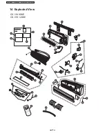
Страница 64: ...14 11 12 13 0 047 AC 230V 50Hz Terminal Board 64 CS YW9DKE CU YW9DKE CS YW12DKE CU YW12DKE...

Страница 65: ...65 CS YW9DKE CU YW9DKE CS YW12DKE CU YW12DKE...

Отзывы: