– 65 –
Setup menus
SYSTEM menu
<SYSTEM>
Item
Setting
No.
Superimposed
No.
Superimposed
Description
display
display
00
WFM SEL
0000
CTL
0001
TC
0002 VIDEO
0003
SYNC
0004
RF-L
0005
RF-R
0006
ENV-L
0007
ENV-R
01
PARA IN
0000
<SUB>
Submenu screen for 01 (PARA IN) menu
00
(PIN1)
0000
REC
01
(PIN2)
0000
PLAY
02
(PIN3)
0000
FF
03
(PIN4)
0000
REW
04
(PIN5)
0000
STOP
05
PIN6
0000
––––
0001
DC FIT_H
0002
UC FIT_H
0003
UD FIT_H
06
PIN7
0000
––––
0001
DC FIT_V
0002
UC FIT_V
0003
UD FIT_V
07
PIN8
0000
––––
0001
422 REM ON
08
PIN9
0000
––––
0001 422 REM OFF
09
(PIN10)
0000
LOCAL ENA
The underline on the setting item denotes the initial setting.
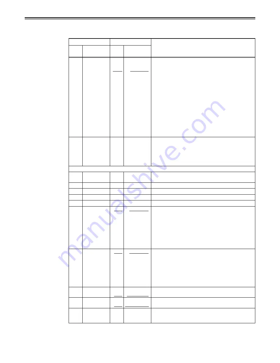
This selects the signal to output from the VIDEO OUT 2
connector.
0: The CTL signal is output.
1: The TIME CODE signal is output.
2: The VIDEO OUT signal is output.
3: The SYNC signal is output.
4: The PB L RF signal is output.
5: The PB R RF signal is output.
6: The PB L ENV signal is output.
7: The PB R ENV signal is output.
<Note>
1. The settings can be changed at any time regardless of the
setup menu item No. 30 (MENU LOCK) setting.
2. The signals which are output during normal playback have
approximately the levels given below.
CTL: 0.1 to 0.3 Vp-p TC: 0.6 Vp-p
VIDEO: 1.0 Vp-p
For allocating what is to be controlled by the pins of the
PARALLEL REMOTE connector. When the STOP button is
pressed, the display transfers to the submenu screen, and
what is to be controlled is selected for each of the pins. To
return from the submenu screen, press the STOP button
again.
0: Used simultaneously with PIN 2 (PLAY); transfers operation
to the recording mode.
0: Transfers operation to the play mode.
0: Transfers operation to the fast forward mode.
0: Transfers operation to the rewind mode.
0: Transfers operation to the stop mode.
0: No control exercised.
1: Switches the picture frame during down-conversion to the
letter box mode.
2: Cuts the top and bottom of the picture frame during up-
conversion in respect of the vertical direction.
3: Switches the picture frame during down-conversion to the
letter box mode and cuts the top and bottom of the picture
frame during up-conversion in respect of the vertical
direction.
0: No control exercised.
1: Switches the picture frame during down-conversion to the
side-cut mode.
2: Switches the picture frame during up-conversion to the side
panel mode.
3: Switches the picture frame during down-conversion to the
side-cut mode and switches the picture frame during up-
conversion to the side panel mode.
0: No control exercised.
1: The 9-pin remote function is enabled.
0: No control exercised.
1: The 9-pin remote function is disabled.
0: Enables all the buttons that can be operated on the front
panel except for RECORDER and PLAYER in the
REMOTE mode.


