background image

1  2  3  4

Basic Operation 

(continued)

Power On Indicator

This LED is illuminated when
the utility condition is normal
and the UPS outlets are pro-
viding clean, protected power.

Line Fault Indicator

This LED will illuminate to warn the user that a
wiring problem such as a bad/missing ground or
reversed wiring exists within the AC receptacle.  
If illuminated, disconnect all equipment and contact
an electrician to insure outlet is properly wired.

Unsafe Voltage Indicator

This LED will illuminate to inform the user that
an unsafe line voltage is present and that the
UPS has switched to battery power.  This could
be either an over-voltage or under-voltage.

Battery Mode Indicator

This illuminates during utility failure or
an unsafe voltage condition, indicating
that the battery is supplying power to
the connected equipment.

AVR Indicator

This indicates that the UPS is operating in automatic voltage regulation mode.  When the led is illu-
minated continuously, it indicates an input over-voltage and the UPS unit reduces (bucks) the volt-
age to the normal operating range.  When the led is flashing, it indicates that the input line voltage
is low and that the UPS is increasing (boosts) input voltage to the normal range.

Load Level Indicator

This is a visual indication of the
UPS load.  

The 

1st

arrow will illuminate when

the load is above 25%, the 

2nd

above 50% and the 

3rd

above

75%.  The 

4th

arrow will flash

when the load is between 85%
and 100%.

Battery Level Indicator

This is a visual indication of the
battery charge.  If battery capac-
ity is under 25%, no indicator
LED will illuminate and UPS
starts beeping (if the audible
alarm is enabled).

3

USA & Canada (800) 472-5555  •  (707) 283-5900  •  Fax (707) 283-5901

FRONT PANEL DISPLAY LED DESCRIPTIONS

REAR PANEL DESCRIPTION

Circuit Breakers for
Overload Protection

Resettable circuit
breakers provide 
optimal overload 
protection.

Non-Critical-Load Outlets

Four battery powered, surge
protected and AVR outlets for
connected equipment insures
temporary uninterrupted oper-
ation of connected equipment
during a power failure.

Critical Load Outlets

Two battery powered, surge
protected and AVR outlets for
critical-load equipment
insures temporary uninter-
rupted operation of connected
equipment during a power
failure.

IR Control Section

Learning Control Switches – Push to program or test the IR function
IR Detector Window – Receives the IR signal to be learned
Indicator LED’s – Indicates learning status
Output Delay Switches – Set the desired time delay between a power failure and
when the IR signals are sent to the connected equipment
IR Output Jacks – Standard 1/8” (3.5mm) mono jack for connection to an IR
flasher (IR flashers not included)

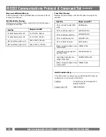
RS232 Serial Communication Port

The serial port allows connection and communication between
the UPS and a HTPC (home theater personal computer) or home
automation system.  If used temporarily during setup (with the
included software), it allows the installer to program a number of
variables including the Critical Load Battery Threshold.  See the
software documentation for more information.

RJ11/RJ45 Jacks

Ports protect stan-
dard telephone line,
modem, or network
cable.

AC Power
Cord Input
Receptacle

Содержание PFPower M1500-UPS-PFP

Страница 1: ...Cinema UPS Owner s Manual 1690 Corporate Circle Petaluma CA 94954 www panamax com M1500 UPS PFP The M1500 UPS PFP is a Programmable Uninterruptible Power Supply Voltage Regulator Power Conditioner Pat...

Страница 2: ...Battery Features pgs 10 11 Diagnostics pg 11 Troubleshooting pg 12 Technical Specifications pg 12 RS232 Communications Protocol Command Set pgs 13 14 15 16 FCC Notice and Warranties Pg 17 Table of Co...

Страница 3: ...e battery can energize hazardous live parts inside even when the AC input power is disconnected CAUTION To prevent the risk of fire or electric shock install in a temperature and humidity controlled i...

Страница 4: ...eptacle wall outlet Make sure the wall branch outlet is protected by a fuse or circuit breaker and does not service equipment with large electri cal demands e g refrigerator copier etc Avoid using ext...

Страница 5: ...dication of the battery charge If battery capac ity is under 25 no indicator LED will illuminate and UPS starts beeping if the audible alarm is enabled 3 USA Canada 800 472 5555 707 283 5900 Fax 707 2...

Страница 6: ...t to both outputs The IR LED s will flash once per second during the delay time and will stop flashing after the IR code is sent 2 If the delay settings are the same for both IR1 and IR2 the IR2 code...

Страница 7: ...d Home Cinema Power Control Software The M1500 UPS PFP has one rear panel serial port that provides the ability to program special functions safely shutdown a home theater PC HTPC or integrate the UPS...

Страница 8: ...mand 12 Follow the on screen instructions 13 Once the software has finished installing remove the disk and restart your computer For Windows NT 4 0 1 Click on Start point to Settings then click Contro...

Страница 9: ...n the HTPC during extended power fail ures This requires a permanent RS232 connection to the HTPC and having the Home Cinema Power Control software running in the background on the HTPC When a power f...

Страница 10: ...for the UPS software 12 Time between power failure and shutdown For use with an HTPC This is the user controllable delay between when the power fails and the software starts the shutdown process If u...

Страница 11: ...tes and times of any scheduled startups and shut downs 7 Delete Clears the selected item from the schedule 3 Turn Off Select the day date and time that you want the computer system to shutdown This is...

Страница 12: ...M1500 UPS PFP 3 year warranty PF Power will replace M1500 UPS PFP batteries if the fail within the 3 year product warranty period For battery replacement information and instructions please contact Pa...

Страница 13: ...boost 13 of input voltage for output regulation while input voltage is from 8 to 15 under nominal AVR Max boost 26 of input voltage for output regulation while input voltage is from 15 to 26 under nom...

Страница 14: ..._____________________________Yes Maintenance free____________________________________________________________Yes Lead acid___________________________________________________________________Yes User re...

Страница 15: ...he battery charge falls below a set threshold refer 2 5 It is desirable to have the ability to switch the power to the outlets on and off to force a hard reboot of equipment Devices such as satellite...

Страница 16: ...pace 20 Hex XX is a number between 25 and 60 represented in ASCII If XX is a valid number between 25 and 60 Action Assigns the battery threshold variable with the value XX Response from UPS BTHRESH SP...

Страница 17: ...is in AVR mode and bucking voltage by 11 Response from UPS AVRBUCK1 CR If the UPS is in BATTERY mode Response from UPS BATTERY CR Request Load Level Status Transmit the load level percentage Send to U...

Страница 18: ...n AVR or BATTERY mode UPS is in AVR boosting 13 UPS is in AVR boosting 26 UPS is in AVR bucking 15 UPS is in BATTERY mode Battery charge falls below critical load threshold Input voltage exceeds high...

Страница 19: ...of three 3 years from the date of purchase that the unit shall be free of defects in design materi al or workmanship and Panamax will repair or replace any defective unit Upgrade Policy Valid only in...

Страница 20: ...1690 Corporate Circle Petaluma CA 94954 Tel 707 283 5900 Fax 707 283 5901 www panamax com...

Отзывы: