background image

5

Palmgren Operating Manual & Parts List

84315

INSTALLATION (CONTINUED)

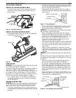
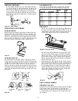
REMOVAL OF SPUR CENTER FROM SPINDLE

To remove the spur center from the spindle, insert the center
removal rod into the spindle and gently tap the center out.
Refer to Figure 7.

REMOVAL OF BEARING CENTER FROM RAM

To remove bearing center from tail stock ram, turn handwheel
counterclockwise. Refer to Figure 8.

POWER SOURCE
WARNING:

Do not connect wood lathe to the power source until

all assembly steps have been completed.

The motor is designed for operation on the voltage and frequency
specified. Normal loads will be handled safely on voltages not
more than 10% above or below specified voltage. Running the unit
on voltages which are not within range may cause overheating
and motor burn-out. Heavy loads require that voltage at motor ter-
minals be no less than the voltage specified on nameplate.

Power supply to the motor is controlled by a single pole lock-
ing rocker switch. Remove the key in the rocker switch to pre-
vent unauthorized use.

GROUNDING INSTRUCTIONS
WARNING:

Improper connection of equipment grounding conduc-

tor can result in the risk of electrical shock. Equipment should be
grounded while in use to protect operator from electrical shock.

Check with a qualified electrician if grounding instructions are
not understood or if in doubt as to whether the tool is properly
grounded.

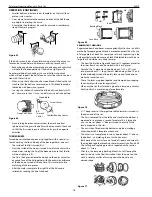
This tool is equipped with an approved 3-conductor cord rated
at 300V and a 3-prong grounding type plug (see Figure 9) for
your protection against shock hazards.

Grounding plug should be plugged directly into a properly
installed and grounded 3-prong grounding-type receptacle, as
shown (Figure 9).

Do not remove or alter grounding prong in any manner. In the
event of a malfunction or breakdown, grounding provides a
path of least resistance for electrical shock.

WARNING:

Do not permit fingers to touch the terminals of plug

when installing or removing from outlet.

Plug must be plugged into matching outlet that is properly
installed and grounded in accordance with all local codes and
ordinances. Do not modify plug provided. If it will not fit in out-
let, have proper outlet installed by a qualified electrician.

Inspect tool cords periodically and if damaged, have them
repaired by an authorized service facility.

Green (or green and yellow) conductor in cord is the grounding
wire. If repair or replacement of the electric cord or plug is nec-
essary, do not connect the green (or green and yellow) wire to
a live terminal.

Where a 2-prong wall receptacle is encountered, it must be
replaced with a properly grounded 3-prong receptacle installed
in accordance with National Electric Code and local codes and
ordinances.

WARNING:

This work should be performed by a qualified electri-

cian.

A temporary 3-prong to 2-prong grounding adapter (see Figure 10)
is available for connecting plugs to a two pole outlet if it is proper-
ly grounded.

Do not use a 3-prong to 2-prong grounding adapter unless
permitted by local and national codes and ordinances.

(A 3-prong to 2-prong grounding adapter is not permitted in
Canada.) Where permitted, the rigid green tab or terminal on
the side of the adapter must be securely connected to a per-
manent electrical ground such as a properly grounded water
pipe, a properly grounded outlet box or a properly grounded
wire system.

Many cover plate screws, water pipes and outlet boxes are not
properly grounded. To ensure proper ground, grounding means
must be tested by a qualified electrician.

Figure 9 – 3-Prong Receptacle

Grounding Prong

3-Prong Plug

Properly Grounded Outlet

Figure 7 – Spur Center Removal

Center
Removal Rod

Spur Center

Bearing Center

Handwheel

Figure 8

Figure 10 – 2-Prong Receptacle with Adapter

Make Sure This
Is Connected
To A Known
Ground

2-Prong Receptacle

Grounding Lug

Adapter

3-Prong Plug

Содержание 84315

Страница 1: ...l l p pa ar rt ts s l li is st t 8 84 43 31 15 5 1 15 5 V VA AR RI IA AB BL LE E S SP PE EE ED D W WO OO OD D L LA AT TH HE E Read carefully and follow all safety rules and operating instructions befo...

Страница 2: ...Remember that being careless for even a fraction of a second can result in severe personal injury BE PREPARED FOR JOB Wear proper apparel Do not wear loose clothing gloves neck ties rings bracelets o...

Страница 3: ...orkpiece and start with a new piece of wood Use extra care when turning wood with twisted grain or wood that is twisted or bowed it may cut unevenly or wobble excessively KNOW YOUR CUTTING TOOLS Dull...

Страница 4: ...the line cord to make sure that the plug is in good condition and that the insulation has not been damaged dur ing transit I IN NS ST TA AL LL LA AT TI IO ON N Refer to Figures 7 12 MOUNTING LATHE TO...

Страница 5: ...istance for electrical shock WARNING Do not permit fingers to touch the terminals of plug when installing or removing from outlet Plug must be plugged into matching outlet that is properly installed a...

Страница 6: ...er supply See wiring diagram Figure 12 for wiring instructions O OP PE ER RA AT TI IO ON N Refer to Figures 13 78 WARNING Operation of any power tool can result in foreign objects being thrown into th...

Страница 7: ...r and drive the spur center into the other end of the wood Make sure the spurs are in the saw cuts Remove the spur center Make sure the centers and the hole in the spindle and the tail stock ram are c...

Страница 8: ...by pulling up on locking handle Remove pin and rotate headstock 90 Insert pin at outboard alignment hole and secure headstock with locking handle USING WOODWORKING CHISELS SELECTION OF CHISELS Better...

Страница 9: ...g edge will con tinue to dig deeper into the work It will dig in until the bite becomes so deep that your hands have difficulty holding the chisel then the improperly supported chisel will begin to bo...

Страница 10: ...e handle bevel side down Keep the base of the bevel against the work It is good practice is to place the skew well over the work pull it back until the edge begins to cut then swing the handle into po...

Страница 11: ...handle This position may be near the middle of the handle or towards the end depending upon the amount of leverage required The position of the hand near the tool rest is a matter of individual prefe...

Страница 12: ...zing cuts are useful to establish approximate finished size diame ters at various points along a workpiece The work can then be turned down to the diameters indicated and be ready for finishing Diamet...

Страница 13: ...edge begins to cut roll skew in the direction of the vee so that the exact portion of the edge which started cutting will travel in a 90 arc down to bottom of the vee Upon reaching bottom of the vee t...

Страница 14: ...be quickly traced around the spindle by touching each line with the pencil After marking use the parting tool to make sizing cuts at all of the important shoulders When learning you will find it best...

Страница 15: ...ining on workpiece CUTTING DOWELS Dowels of any size can be turned quickly with the simple jig shown If the stock is prepared as a split or quartered turning half round and quarter rounds will be prod...

Страница 16: ...step is to remove as much wood as possible by boring into the center with the largest wood bit available This can be accomplished as illustrated in Figure 59 Be careful to measure in advance the depth...

Страница 17: ...and it is turned in the usual manner All surfaces are cut except the back side which is against the mounting block The work is then removed from the mounting block An auxiliary chuck of softwood is no...

Страница 18: ...ight fit of the lid can be relieved by sanding the lip of the body SEGMENTED TURNINGS Segmented bowls and boxes are exceptionally attractive and this method of preparing wood stock is more economical...

Страница 19: ...duced all having a distinctive surface pattern preformed tools will speed the work and assure uniformity Patterns like those illustrated can be created by grinding thin 020 to 010 gauge aluminum strip...

Страница 20: ...omponent CLEANING Keep machine and workshop clean Do not allow sawdust to accu mulate on the tool Keep centers clean Be certain motor is kept clean and is frequently vacuumed free of dust Use soap and...

Страница 21: ...f round 2 Workpiece has too much wobble 3 Operator using bad technique 4 Cutting motion is against the grain of the workpiece 5 Workpiece is too long and thin workpiece is deflected by tool pressure W...

Страница 22: ...1 60 19 21 21 20 20 22 36 80 83 79 78 77 28 69 69 26 27 29 31 34 72 30 32 33 47 40 43 43 50 51 81 59 49 45 57 58 52 53 54 55 56 73 74 75 76 70 70 71 46 42 41 7 8 8 8 38 39 37 37 35 67 68 23 2 1 1 3 12...

Страница 23: ...djusting Rod 18036 00 1 42 Retainer 18037 00 1 Ref No Description Part No Qty 43 6 1 0 x 12mm Flat Head Screw 08567 00 4 44 5 0 8 x 6mm Set Screw 03069 00 1 45 Gear 18038 00 1 46 5 0 8 x 10mm Flat Hea...

Страница 24: ...63 64 76 77 62 61 60 19 21 20 22 36 65 66 28 69 26 27 29 31 34 72 30 32 33 47 40 43 50 51 59 49 45 59 57 58 58 52 53 53 54 55 56 73 74 75 70 71 46 42 41 7 8 38 39 65 37 35 67 68 23 2 1 3 12 12 18 17...

Страница 25: ...ain 18084 00 1 33 Rear Cover 18085 00 1 34 Upper Rear Cover 18086 00 1 35 5 0 8 x 12mm Socket Head Bolt 1 36 Spacer 18087 00 1 37 Index Pin Lever 18088 00 1 38 5 0 8 x 30mm Socket Head Bolt 2 39 Block...

Страница 26: ...26 Palmgren Operating Manual Parts List 84315 NOTES...

Страница 27: ...27 Palmgren Operating Manual Parts List 84315 NOTES...

Страница 28: ...charge To order parts for a non warranty repair please contact your preferred Palmgren distributor To obtain the names of Palmgren distributors or to arrange warranty return please call Palmgren Stee...

Отзывы: