background image

ILSL 33/44 Owner‘s Manual                                                                      


Rev.1.1


35 


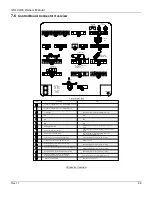
7.6 

Control Board Connector Overview  

   FOOT 
CONTROL

WARNING 
 LIGHTS

CONTROL 
     BOX

HAND HELD
REMOTE (HHR)

POWER PACK

POSITIVE for PC BOARD
(black #2 to 2 
and black # 4 to 27)

CYLINDERS
LIFT 15 (2 ea)

BL - Blue
BR - Brown
SW - Black
GE - Yellow
GN - Green
- Negative
+ Positive

Power LED

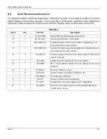
Control Board Codes:

System ok / ON/OFF switch off, (or missing bridge J11/2<->4)

System ok / ON/OFF switch on, (or bridge J11/2<->4)

Low Voltage

Warning lights shorted

Short in on-off switch or aux port

General short in electrical wiring

Emergency program (all sensors are bypassed).
Activation by: Press Open+Lower>10 seconds

Diagnosis mode activated

Defect at motor solenoid detected during lifting

Voltage V02 (J1 pin 2) is missing, defective fuse

Defect at opening, valve (S3/S4) or motor relay 
detected during opening

S5 valve detected during closing or motor solenoid defective

S5 valve detected or defect at lowering valve (S1/S2)

Cab switch: off/on (or disconnect bridge J11/2<->4)

ON/OFF switch (or disconnect bridge J11/2<->4) or close
tail lift

Cab switch: off/on (or disconnect bridge J11/2<->4) or close
tail lift

Cab switch: off/on (or disconnect bridge J11/2<->4) or
voltage interruption MBB control

Cab switch: off/on (or disconnect bridge J11/2<->4)

Automatically when the valves are back to normal

Replace the fuse

Automatically when the valves are back to normal

Automatically when the valves are back to normal

Automatically when the valves are back to normal

Removing service connector

Code

Description

Reset

SLIDE

UP

N/A

N/A

N/A

N/A

N/A

N/A


Connector Overview 


Содержание ILSL 33/44

Страница 1: ...ILSL 33 44 OWNERS MANUAL 11 14 ...

Страница 2: ...it www palfinger com for up to date information and notifications If you received this product with damaged or missing parts contact Palfinger Liftgates at 888 774 5844 Parts Order liftgateparts palfinger com Technical Support technicalapplications palfinger com PALFINGER Liftgates LLC 15939 Piuma Ave Cerritos CA 90703 Tel 888 774 5844 Fax 562 924 8318 PALFINGER Liftgates LLC 572 Whitehead Road Tr...

Страница 3: ... Optional 16 5 5 3 Button Flush Mount Control Side Mount Optional 17 6 Preventive Maintenance and Quick Check 18 6 1 Maintenance and Care 18 6 2 Lubrication 19 6 3 Checking and Changing the Oil 20 6 3 1 Recommended Hydraulic Fluids 20 6 4 Decal Placement and Inspection 22 6 5 Quick Check List 24 7 Troubleshooting 25 7 1 Liftgate will not power on 25 7 2 ON OFF switch is ON but all functions are de...

Страница 4: ...chematic Discontinued 38 7 8 1 Slide Out Function 39 7 8 2 Lower Down 39 7 8 3 Lift Up Function 39 7 8 4 Slide In Function 39 7 8 5 Push Pull Valving Discontinued 40 8 Needed Information for Ordering Spare Parts and Repairs 41 8 1 Ordering Spare Parts 41 8 2 Repairs 41 9 Warranty 41 10 Contact Address 42 ...

Страница 5: ...sion springs each on one side one support folding the other unfolding operation Lifting actions are carried out by hydraulic cylinders mounted on the lift arms The gate is equipped with swing fixtures mounted to the bottom on each lift cylinder This enables the platform to lower down the tip towards the ground The hydraulic cylinders are equipped with solenoid operated valves located at the port o...

Страница 6: ... have read and are familiar with the operation instructions If you do not have a copy of the instructions please obtain them from your employer distributor or lessor as appropriate before you attempt to operate the lift 2 Be certain the vehicle is properly and securely stopped before using the lift 3 Always maintain the liftgate and inspect it for damage before usage If there are signs of improper...

Страница 7: ...form To push loads To carry people Only the operator may travel on the platform To clear snow Please read through the operational and technical description of the PALFINGER Liftgates Liftgate Company Information Company Name Advisor Name Trailer Year Make Model Liftgate Information Liftgate Serial Number Liftgate Model Number Date of Purchase Date of Installation ...

Страница 8: ...t symbol is used to address practices not related to personal injury In this manual we use it to alert you to potentially hazardous situation which if not avoided may result in property damage NOTICE without the safety alert symbol is used to address practices not related to personal injury In this manual we use it to alert you to special instructions steps or procedures Improper operation of this...

Страница 9: ...anual Rev 1 1 9 3 General View of Liftgate 3 1 ILSL Liftgate Overview Steel Main Aluminum Tip Platform Sub Frame Mount Assembly w Rails Hyrdraulic Pump Box Mount Tube Liftarm Parallel Arm Battery Box ILSL Liftgate Overview ...

Страница 10: ...int of maximum load is rated at a defined distance The center point of maximum load is at 24 from the outside of the trailer body to center of load Trailer Body Load 24 Center Point of Load By increasing this distance the maximum load of the lift gate is decreasing An overview about the rating depending on the distance from the end of the platform is shown in the following load diagram Load Diagra...

Страница 11: ...ILSL 33 44 Owner s Manual Rev 1 1 11 NOTES ...

Страница 12: ...ut off switch must be turned off when liftgate is not in use Keep platform in horizontal position when loading and unloading Do not overload refer to capacity decals Loading Position Lower platform Slide out liftgate Unfold platform Storage Position In down position fold up platform tip Slide in liftgate Raise platform Max Capacity on Platform Platform Load 24 2 Rotate the Lift button Down to lowe...

Страница 13: ...ator must use the 2 Button Hand Held Remote HHR to lift the platform load up and down Toggle switches and Foot Controls may also be used if these options have been installed If using the Toggle Switch or Foot Controls see pages 13 for operating instructions 7 Press and hold the Top white button on the 2 Button Hand Held HHR Control to raise the platform cargo Place the control on the holster while...

Страница 14: ...wn Slide Lift In Out 2 Use the Slide button In until the sliding plates hit the stop bolt in the rear of the sliding rail Stop Bolt Up Down Slide Lift In Out 3 When the sliding plates have stopped and reached the stop bolt in the rear use the Lift button Up to secure the platform flush with the upstops until the upstop is compress and release the button 1 2 Compression of Upstop Up Down Slide Lift...

Страница 15: ...hold wait three seconds before stepping on the front foot control If the platform is not responding to the controls within three seconds repeat steps above Front Rear Front Foot Control RearFoot Control Raise Platform Lower Platform Front Foot Control RearFoot Control 5 3 Toggle Switch Switches Optional 1 Toggles switches are an alternative to the 2 Button HHR Control 2 Toggles switches only raise...

Страница 16: ...ntrol Vertical Mount Optional Raise Platform Push and hold Top button Lower Platform Push and hold the Bottom button Slide In Platform Push and hold the Top and Middle buttons simultaneouly Slide Out Platform Push and hold the Botton and Middle buttons simultaneouly ...

Страница 17: ...trol Horizontal Mount Optional Raise Platform Push and hold Top button Lower Platform Push and hold the Bottom button Slide In Platform Push and hold the Top and Middle buttons simultaneouly Slide Out Platform Push and hold the Botton and Middle buttons simultaneouly ...

Страница 18: ...he liftgates longevity it is important to maintain and perform preventive care as indicated below Recommended bases for inspection and maintenance Depending on use Daily Monthly Quarterly Cleaning x General lubrication of pins and bushings x Oil level inspection x Oil change x Check hydraulic hoses and pipes for leaks x Check controls and connections x Check pins and pin retaining bolts x Check ba...

Страница 19: ...nder Lubricate all points with the platform at ground level Oil reservoir Inside 4 zerks 1 Cylinder 1 Lift arm 1 Parallel arm 1 Swing fixture 3 zerks 1 Cylinder 1 Lift arm 1 Parallel arm 4 zerks 1 cylinder 1 Lift arm 1 Parallel arm 1 Swing fixture 3 zerks 1 cylinder 1 Lift arm 1 Parallel arm IN OUT IN Grease 12 places 3 in the mount frame 3 in the cylinder platform area IN OUT Oil level in the pow...

Страница 20: ...he reservoir and into an approved container Screw the oil drainage bolt back 3 Unscrew the oil filler cap Use a good quality fluid based on your location refer to the recommended fluids table The fluid level should be between marks 5 and 7 when the platform is at ground level 4 Change oil at least once a year preferably in the fall before the weather gets cold 6 3 1 Recommended Hydraulic Fluids TE...

Страница 21: ...ILSL 33 44 Owner s Manual Rev 1 1 21 NOTES ...

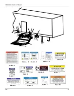
Страница 22: ...ol Vertical Mount if applicable must be located directly above control D 1 ATG SWILFP H 3 Button Remote Control Horizontal Mount if applicable must be located directly above control E 2 ATG XXXX Capacity please check the serial number plate to find out your specific capacity F 1 ATG CAB Liftgate Shut Off located next to shut off switch G 1 ATG BKR Max Circuit Breaker Reset must be located at the c...

Страница 23: ...ILSL 33 44 Owner s Manual Rev 1 1 23 Decal E Decal F Decal A Decal H Decal I Decal D Decal G Decal B Decal C Decal J Decal K Decal L Decal M G A F E H I H E I D M K L J ...

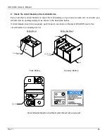
Страница 24: ...n or replace components if needed If you perform work on any hydraulic components bleed the air out of the system by operating all functions several times 7 Check all electrical connections Clean and protect battery terminals and check for tightness 8 Inspect all the terminals on the solenoid operated valves at the port of the cylinder Lubricate the terminals for better protection from oxidation i...

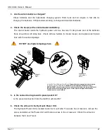
Страница 25: ...ctive objects on or near the battery connections 7 1 Liftgate will not power on 1 Check the shut off switch Turn ON the ON OFF switch located in the control box On Off Switch Lift Slide In Out Up Down For questions regarding operation call 888 774 5844 ILSL To operate this liftgate read and understand the operating decals and manuals Make certain the platform is clear before operating the lift Lif...

Страница 26: ...d an auxiliary battery kit as shown in the illustration below If circuit breaker reset tab is exposed push it back in as shown on the decal ATG BKR next to the circuit breaker or on battery box lid Circuit Breaker Location Circuit Breaker Location Battery Box Buss Bar Jumper Battery Mount Battery Box Mount Truck Battery Auxiliary Battery Reset Tab Circuit Breaker Needs to be Reset when Reset tab i...

Страница 27: ...ntrol Board Replace when metal bridge is broken In Line ATC Fuse 15 Amp at Control Board Replace with same amperage fuse when necessary In Line ATC Fuse 20 Amp at Battery Replace with same amperage fuse when necessary NOTICE DO NOT attempt to jump in line fuses with other objects other than the specified fuse s DO NOT increase the amperage rating of fuse Serious harm to the liftgate will result wh...

Страница 28: ...g hand held control at J31 Remove J1 plug for 5 seconds Reinstall J1 try main control board switches If gate operates the problem is in the hand held control or its wiring 2 Short in control box wire remove J30 plug Remove J1 plug for 5 seconds Reinstall J1 try hand held remote If gate operates the problem is in the control box swtiches or harness After disconnecting plugs reboot board by unpluggi...

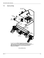
Страница 29: ...tion Switch Ground Ground In Line ATC Fuse 20 Amp Replace with same amperage fuse when necessary Resetable Circuit Breaker 150 Amp Min Replace with same amperage breaker when necessary Ground For optimal grounding ground all batteries and power units to the body side rails of the vehicle NOTICE DO NOT attempt to jump in line fuses with other objects other than the specified fuse Do not increase th...

Страница 30: ... ATC Fuse 20 Amp Replace with same amperage fuse when necessary Resetable Circuit Breaker 150 Amp Min Replace with same amperage breaker when necessary Ground For optimal grounding ground all batteries and power units to the body side rails of the vehicle NOTICE DO NOT attempt to jump in line fuses with other objects other than the specified fuse DO NOT increase the amperage rating of fuse Serious...

Страница 31: ... and Gr Yl go to ground Aux Batteries Ground In Line ATC Fuse 20 Amp Replace with same amperage fuse when necessary Resetable Circuit Breaker 150 Amp Min Replace with same amperage breaker when necessary NOTICE DO NOT attempt to jump in line fuses with other objects other than the specified fuse DO NOT increase the amperage rating of fuse Serious harm to the liftgate will result when standard prac...

Страница 32: ...es Ground In Line Fuse In Line ATC Fuse 20 Amp Replace with same amperage fuse when necessary In Line ATC Fuse 40 Amp Replace with same amperage fuse when necessary Resetable Circuit Breaker 150 Amp Min Replace with same amperage breaker when necessary NOTICE DO NOT attempt to jump in line fuses with other objects other than the specified fuse s DO NOT increase the amperage rating of fuse Serious ...

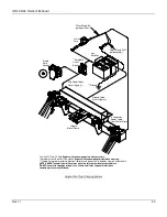
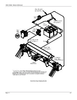
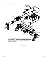
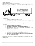
Страница 33: ...ire circuit on tractor including ground 2 Trailer Test Ground battery load tester on trailer chassis point C Connect positive cable on positive pole of single pole plug receptacle on trailer B Run load test This will test entire circuit on tractor including circuit breakers and ground between trailer batteries and trailer chassis 3 Tractor and Trailer Charging system test while connected Ground ba...

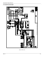
Страница 34: ... Rev 1 1 34 7 5 Electrical Schematic UP DOWN SLIDE IN SLIDE OUT DOWN DOWN SLIDE IN SLIDE OUT UP UP DOWN Wiring Schematic ILSL 5 2 Up 6 2 Down 4 Power 12V NOTE REPLACE FUSES WITH SAME AMPERAGE WHEN NECESSARY Electrical Schematic ...

Страница 35: ... during lifting Voltage V02 J1 pin 2 is missing defective fuse Defect at opening valve S3 S4 or motor relay detected during opening S5 valve detected during closing or motor solenoid defective S5 valve detected or defect at lowering valve S1 S2 Cab switch off on or disconnect bridge J11 2 4 ON OFF switch or disconnect bridge J11 2 4 or close tail lift Cab switch off on or disconnect bridge J11 2 4...

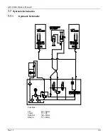
Страница 36: ...ILSL 33 44 Owner s Manual Rev 1 1 36 7 7 Hydraulic Schematics 7 7 1 Hydraulic Schematic Functions Lift S4 Motor Lower S1 S2 Slide Out S8 Motor Slide In S7 Motor S8 S7 S4 B A A B D M A A ...

Страница 37: ...inders get energized The gate is designed to lower down by gravity It will push the hydraulic oil out of the lift cylinder into the reservoir The oil passes the solenoid release valves S1 and S2 7 7 4 Lift Up Function Motor starts running oil pressure exits pump and motor to the release valves S1 and S2 are forces the fulid to push the lift cylinders to extend The platform raises up 7 7 5 Slide In...

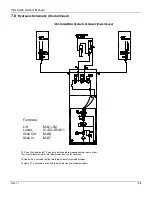
Страница 38: ... They have to be activated for fluid to go through them in either direction To slide out S8 is activated to allow fluid to both sides of retractable cylinders To slide in S7 is activated to allow fluid to piston rod side of retractable cylinders Functions Lift M S1 S2 Lower S1 S2 S5 S11 Slide Out M S8 Slide In M S7 ILSL Pump Motor Hydraulic Schematic Discontinued ...

Страница 39: ...l out of the lift cylinder into the reservoir The oil passes the solenoid release valves S1 and S2 It also has to pass the energized S11 valve in the back of the mount frame and the shift valve S5 at the pump 7 8 3 Lift Up Function Motor starts running and double locking release valves S1 and S2 are energized The pressure is on input A at the valve block The oil passes the S11 valve and sets press...

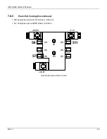
Страница 40: ...l Rev 1 1 40 7 8 5 Push Pull Valving Discontinued S 8 energizes open and S7 closes to slide out S 7 energizes open and S8 closes to slide in S11 AH AK BK AH AK BK BV AV S8 S7 J42 80 J1 12 J42 81 Valve Block Setup at Main Frame ...

Страница 41: ...able to determine that the warranty claim is justified as defined by its warranty conditions PALFINGER Liftgates does this by inspecting the defected parts which are sent back to PALFINGER Liftgates freight prepaid as well as the written description of the problem which must have been filled out in full The parts that are sent back to PALFINGER Liftgates marked with serial number and address becom...

Страница 42: ...18 Fax 562 924 8318 E mail parts order liftgateparts palfinger com E mail technical support technicalapplications palfinger com 572 Whitehead Road Trenton NJ 08619 Phone 609 587 4200 Fax 609 587 4201 E mail parts order liftgateparts palfinger com E mail technical support technicalapplications palfinger com ...

Отзывы: