


66
10.3. Setting tilt switch B13
Note:
If the tilt sensor
B15
is present on the torsion frame of your tail lift, there is
no need to set the tilt switch
B13
.
►
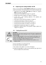
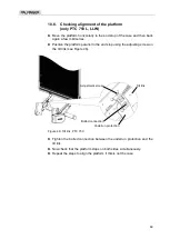
Move the platform to the position horizontally approx. 250 mm above the
ground as presented in Figure 43, page 66.
Figure 43: Tilt switch
B13
(1)
►
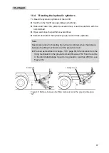
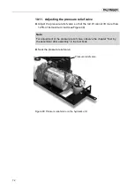
Release the screw on tilt switch
B13
on the right control rod of the torsion
frame (see Figure 44).
Figure 44: Tilt switch
B13
(2)
►
Adjust tilt switch
B13
so that it is exactly horizontal.
►
Retighten the screw on tilt switch
B13
. Observe the tightening torque of
9 Nm.
►
Edge the safety plate over the control rod of the torsion frame so that tilt
switch
B13
is secured in position.
Tilt switch
b13
appr
ox
. 2
50 m
m
Tilt switch
b13
Bolt
Safety plate