Table of Contents
file:///C|/PACH-CO.COM-2022-B/online_manual/qvoip_manual.htm[3/24/2022 1:59:26 PM]
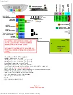
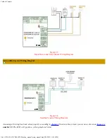
1. Input Power 12VAC 40VA (supplied)
2. Battery Back-up 12VDC 4Ahr
3. Relay 2 dry contact (door strike, gate operator)
4. Relay 1 dry contact (door strike, gate operator)
5. Telephone Out (connect to next system)
6. Telephone input connect to No.15 on AATA2
7. Aux 1 and Aux 2 connect such as infrared sensor, exit switch or postal lock
8. Door Sensors,
these are not for door strikes
9. RS-485 coonect up to 8 slave units such as USCR, UCRM, USKPR and USKP
10. 26-Bit Wiegand Input (card reader is included)
11. Factory use only to power the QWCM IP module.
12. AATA2 input power 5VDC 3.0A (supplied)
13. Internet port, connect to the router
14. N/A
15. Dial tone out, connect to No. 6
Figure 2.1
General Wiring Diagram

