background image

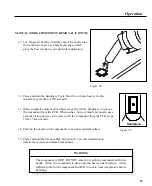
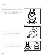
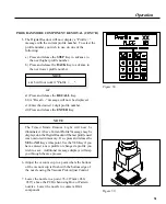
17. When complete solder melt is observed, release the handpiece Cycle

Switch (to cease air flow) and gently lift the handpiece from the PCB.

NOTE

Any required preheating should be
completed before advancing beyond this
point.

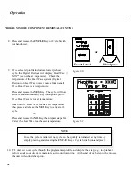
Figure 38.

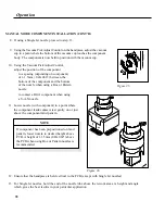
16. If vacuum is being used to hold component, depress and hold the Vacuum

Pick Switch for 0.5 second (minimum) to stop vacuum and release the
component.  Release the Vacuum Pick Switch.

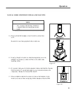
14. Press and hold the handpiece Cycle Switch to activate heat

cycle.

15. If using a Single Jet nozzle in a hand held operation, move the

handpiece as necessary to direct air flow to the solder areas
requiring reflow.

Heated air is now being applied to the rework area.

Handpiece

Handpiece

Figure 37.

39

Operation

MANUAL MODE COMPONENT INSTALLATION (CONT'D)

Содержание TF 200

Страница 1: ...OPERATION MAINTENANCE MANUAL PROGRAMMABLETHERMOFLO TF 500 TF 500E Systems TF 200 TF 200E Units ...

Страница 2: ...MANUAL NO 5050 0420 REV C i ...

Страница 3: ...ermoFlo Cubby Kit 12 Hose Retention Kit 12 QuickFit Nozzle Adapter 14 Optional Accessories 14 Power Up 15 Quick Start 16 Introduction 16 Manual Mode Of Operation 16 Timed Mode Of Operation 18 Program Mode Of Operation 20 Process Development 22 Introduction 22 Profile Development 22 Suggested Starting Parameters 23 Profile Control Chart 24 Profile Log 25 General Process Guidelines 26 Component Prep...

Страница 4: ... Entering Editing A Profile 58 Set Up Mode 72 Introduction 72 Entering Set Up Mode 72 Locks 72 Profile Deletion 76 Calibration 77 Corrective Maintenance 78 Digital Readout Message Codes 78 Unit 79 Replacement Parts 80 ThermoFlo Unit 80 Parts Consumables 82 Systems Accessories 83 Available Nozzles 84 Manual Improvement Comment Form 87 TABLES TABLE PAGE Table 1 Digital Readout Message Codes 78 Table...

Страница 5: ...Wave PACE SensaTemp Snap Vac Sodrtek Sodr X Tractor ThermoFlo ThermoJet ThermoTweez Toolnet Visifilter 2001 PACE Incorporated Laurel MD All rights reserved Printed in the U S A For any questions regarding this Operation Maintenance Manual contact your local authorized PACE distributor or contact PACE directly at the appropriate address listed below PACE USA 9893 Brewers Court Laurel Maryland 20723...

Страница 6: ...PACE Customer Support directly at Tel 301 490 9860 or FAX 301 604 8782 THERMOFLO QUICK START The ThermoFlo Unit is easy to operate and can be quickly set up for use in Manual mode or Timed mode of operation To begin operation of your new unit quickly perform the Set Up and Quick Start procedures detailed on pages 10 21 of this manual The Quick Start section of this manual provides condensed proced...

Страница 7: ...t hand A multi level password lock out prevents unauthorized changes and an audible countdown timer indicates end of cycle Multi Mode Operation Manual Mode For fast and simple hand held installations and removals Timed Mode For process control with user specified cycle time and automatic vacuum pick up operation Program Mode For full process control Eighty 80 user defined profiles including parame...

Страница 8: ...ource 230VAC work platform board holder tools and accessories Power Requirements PPS 95 Power Source Operates on 97 127 VAC 60 Hz 115 VAC version 575 Watts maximum at 120 VAC 60 Hz PPS 95E Power Source Operates on 197 264 VAC 50 Hz 230 VAC version 575 Watts maximum at 230 VAC 50 Hz Air Temperature Range 93 C 427 C 200 F 800 F Timing Control 10 to 999 seconds with 1 second resolution does not inclu...

Страница 9: ... and Timed Modes and deactivates the air flow when pushed during a reflow cycle Also initiates selected rework Profile when in Program Mode 8 TEMPERATURE SCROLL UP KEY Increases the Set Temperature in one then ten degree if key is held down increments 9 TEMPERATURE SCROLL DOWN KEY Decreases the Set Temperature in one then ten degree if key is held down increments 10 BLOWER SPEED SCROLL UP KEY Incr...

Страница 10: ...rough all stored profiles g BACK Key Backs the user up to the previous step in the programming sequence Also allows the user to step back through profiles stored in memory h ENTER Key Performs storage of profile at the end of the programming sequence 15 MODE ESC KEY Steps through the modes of operation and is used as an escape key when editing process control profiles 16 DIGITAL READOUT A 2 line L...

Страница 11: ...connected from the workpiece or work surface as part of a static control program 21 GFI LIGHT Illuminates Green in color when unit is powered on Light goes off when a handpiece ground fault heater fault or blower fault is detected and heater operation is disabled 22 HANDPIECE CABLE ENTRY Hard wired cable entry from ThermoFlo handpiece to power source 23 HEAT WAVE CONNECTOR Provides connection to P...

Страница 12: ... a means to lift or place components 29 HEAT SHIELD Protects the operator from unintentional contact with the heater 30 VACUUM CUP Provides positive holding of components for positioning during the replacement process and for lifting of the component during the removal process 31 NOZZLE ASSEMBLY Directs heated air from the heater assembly to the solder joint areas for soldering or desoldering of c...

Страница 13: ...Used to indicate a statement of company recommendation or policy The message may relate directly or indirectly to the safety of personnel or protection of property NOTE is not associated directly with a hazard or hazardous situation and is not used in place of CAUTION WARNING or DANGER CAUTION Used to indicate a hazardous situation which may result in minor or moderate injury May also be used to a...

Страница 14: ...lps to prevent unintentional contact with the heater 3 Utilize all standard electrical safety precautions when using this or any other electrical equipment 4 Always use this system in a well ventilated area A fume extraction system such as those available from PACE are highly recommended to protect personnel from solder flux fumes 5 Exercise proper precautions when using chemicals e g solder paste...

Страница 15: ... from its shipping container s Store the shipping container s in a convenient location Reuse of these containers will prevent damage if you ship or store the system 2 Set the ThermoFlo unit on a convenient work bench 3 Place the POWER Switch on power source rear panel in the OFF or 0 position 4 Inspect all system components to check for shipping damage and to ensure that all purchased components s...

Страница 16: ...e and just behind the two 2 rubber feet on the power source case 4 Slide the 2 mounting slots in the Angle Bracket beneath the 2 Thumb Screws You may need to adjust the Thumb Nuts to provide enough space between the Thumb Nuts and the power source case 5 Tighten Thumb Nuts to secure bracket in position 6 Remove the paper backing from the two 2 rubber feet and place in position on the Angle Bracket...

Страница 17: ...ource 3 Place the Cubby onto the side of the power source inserting the two 2 Mounting Screws through any two 2 opposing Mounting Holes in the Cubby Bracket The multiple mounting holes allow the user to adjust the Cubby as desired 4 Install a Thumb Nut onto the end of each Mounting Screw 5 Adjust Cubby Bracket flush with front of power source Tighten Thumb Nuts to secure bracket in position HOSE R...

Страница 18: ...ng Collar over end of Slide Tube with beveled end of collar facing up and with Collar Access Hole in line with Tube Access Hole 7 Insert end of Slide Rod through top of Locking Collar and into the Slide Tube Slide rod fully into the tube 8 Install the Locking Screw into the Locking Collar Ensure that the collar is positioned properly on the tube see step 6 Tighten the Locking Screw and check the S...

Страница 19: ...andpiece heater as shown 2 Position the QuickFit Adapter so the Line on the heater is aligned with one of the 3 lines 1 long 2 short lines on the Locking Collar Tighten Collar Locking Screw to secure adapter in position Figure 8 OPTIONAL ACCESSORIES Install all purchased options e g work platform lights camera system at this time A separate installation instruction manual PACE part number 5050 042...

Страница 20: ... insure operator safety the AC supply receptacle must be checked for proper grounding before initial system operation 2 Plug the power cord into the AC supply receptacle 3 Turn the Power Switch to the ON I position 4 Test the system for proper operation Refer to the Quick Start portion of this manual Figure 9 Set up 15 ...

Страница 21: ...al Manual Mode of Operation REMOVAL 1 Install proper Nozzle onto ThermoFlo Handpiece 2 Turn Power Switch ON Press MODE ESC Key until Manual Mode Light illuminates 3 Adjust Set Temperature and Blower Speed as desired using Scroll Keys See Figure 10 1 Figure 10 4 Lower Nozzle over component slightly above component leads to direct air flow to solder joints See Figure 10 2 5 Press and hold handpiece ...

Страница 22: ...ed as desired using Scroll Keys See Figure 11 1 4 Position replacement component on prepared land pattern See Figure 11 2 5 Lower Nozzle to direct air flow to solder joints 6 Press and hold handpiece Cycle Switch to initiate reflow cycle See Figure 11 3 7 When complete reflow of solder joints is observed release handpiece Cycle Switch and lift handpiece Figure 11 17 Quick Start ...

Страница 23: ...he cup using the Vacuum Pick Adjust Control to a point where the bottom of the cup is flush with the bottom edge of the nozzle See Figure 12 2 5 Lower Nozzle over component slightly above component leads to direct air flow to solder joints Ensure contact between the vacuum cup and the component 6 Press and release handpiece Cycle Switch to initiate reflow cycle See Figure 12 3 Figure 12 NOTE Five ...

Страница 24: ...nd Cycle Time as desired using Scroll Keys See Figure 13 1 4 When using a single jet Nozzle place component by hand and proceed to step 7 5 Position replacement component directly beneath square to nozzle 6 Lower Vacuum Cup to contact component Press Vacuum Switch to activate vacuum and grasp component Adjust height of component to nozzle See Figure 13 2 7 Lower Nozzle to direct air flow to solder...

Страница 25: ...4 Program Mode Of Operation The following is a simple basic flow chart of the Program Mode of Operation Use this as a quick reference when using a rework profile previously stored in unit memory 20 Quick Start ...

Страница 26: ...21 Quick Start ...

Страница 27: ...odes Once the Profile is entered into memory the program can be quickly initiated in Program Mode Up to 80 user defined profiles may be stored in microprocessor memory Profile Development 1 The Profile Control Chart details the complete parameters for a developed profile The Profile Log is a quick reference log sheet detailing basic profile information including stored profile number on a number o...

Страница 28: ...e PCB Type Reflow Cycle Outline Type Recommended Type Remove or Install Temperature and Blower Speed Low Mass Medium Mass High Mass Time sec PBGA Appropriate Size V A N Nozzle Remove Temperature C 371 371 371 77 Blower Speed 5 5 5 Install Temperature C 371 371 371 90 Blower Speed 3 3 4 PLCC J Lead Appropriate Size Box Nozzle Remove Temperature C 371 371 371 30 Blower Speed 7 8 8 Install Temperatur...

Страница 29: ...d Soak Yes No Temp Time sec Blower Speed Reflow Yes No Temp Time Blower Speed Install Only Vacuum Release Lower Pump On Off Cool Down On Off Approved By Time sec Blower Speed Date Comments Instructions Copyright 1997 PACE Inc Laurel Maryland All rights reserved Printed in U S A Profile Control Chart Duplicate this page and complete the copied form DO NOT fill out the copy in this manual Process De...

Страница 30: ...Process Remove or Install Mode Profile Set Temperature Blower Speed Cycle Time sec Preh Requi PROFILE LOG Duplicate this page and complete the copied form DO NOT fill out the copy in this manual Figure 17 Process Development 25 ...

Страница 31: ...der paste deposition to remove any volatiles e g solvents in the paste The PACE Heat Wave HS 200 system is highly recommended for this preheating application Component Positioning The ThermoFlo has the capability of placing many SMD components properly In some instances e g fine pitch FlatPack placement however the user may prefer to position a component and solder tack it in place prior to final ...

Страница 32: ...Overcome the heat dissipation characteristics of the assembly 4 Minimize adjacent melts on densely populated assemblies The assembly undergoing repair must be heated for a length of time sufficient to saturate at the preheat temperature required The PCB preheat temperature normally used is 100 C 212 F for epoxy glass substrates and 120 C 248 F for ceramics and polyimides Although many different me...

Страница 33: ...d password Lock Mode Feature which prevents the changing of operating mode Manual Timed or Program without entry of the stored password Manual Mode Mode of operation in which the operator sets only Operating Temperature and Blower Speed parameters The operator then manually performs a rework operation Operating Temperature The true air stream temperature as it exits the handpiece heater assembly T...

Страница 34: ...ode of operation in which the operator can quickly and easily enter change or delete system parameters e g password C F display profile deletion Soak The application of heated air from the ThermoFlo handpiece to saturate the rework area after preheat top and or bottom and prior to initiation of a Reflow Cycle in the Program Mode Timed Mode Mode of operation in which the operator enters the Operati...

Страница 35: ...r removal replacement of BGA components Box Nozzles Used for removal replacement of surface mount components having solder connections on 4 sides of the component e g QFPs PLCCs Pattern Nozzles Used for removal replacement of surface mount components having solder connections on 2 sides of the component e g SOICs Single Jet Nozzles Available in straight curved and flat end versions these nozzles a...

Страница 36: ... the component Vacuum cups are consumable items which deteriorate over a period of time Refer to the Replacement Parts section of this manual when replacement is required Figure 20 Template Selection Alignment Templates are used as an aid in aligning V A N Nozzles to the PCB Assembly when installing Ball Grid Arrays BGAs The I D Inside Dimension of the template should match the perimeter of the BG...

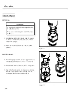
Страница 37: ...dapter use Rubber Pad if nozzle is hot Gently twist the nozzle as shown to lock nozzle in place Nozzle Changeout REMOVAL WARNING NeverremoveaheatedNozzleusingbarehands Use the Rubber Pad Never use a wrench or pliers when removing a Nozzle 1 Holding the Rubber Pad gently twist the nozzle as shown The Nozzle will easily release from the Nozzle Adapter 2 Place the Nozzle still hot on a heat resistant...

Страница 38: ...yond this point Figure 24 2 Set unit POWER Switch on power source rear panel to the ON position Figure 23 3 Press and release MODE ESC Key as necessary until the MANUAL Mode Light is illuminated 4 Adjust the Set Temp as desired using the Temperature Scroll Up and Down keys Press and hold the key observe the Digital Readout as the Set Temperature increases or decreases in 1 and then 10 increments a...

Страница 39: ...bottom of the vacuum cup is flush with the bottom edge of the nozzle 8 Hold the handpiece vertical to the PCB 9 Lower the nozzle to a point 1mm 040 above the PCB when using a Box nozzle to a point depending on component 1 1 5mm 040 060 above the PCB when using a Pattern nozzle to contact a BGA component when using a V A N nozzle 10 Press and release handpiece Vacuum Pick Switch to activate vacuum ...

Страница 40: ...gure 29 Handpiece 12 Press and hold the handpiece Cycle Switch to activate heat cycle the maximum cycle time is 999 seconds 13 When complete solder melt is observed gently lift the handpiece to remove the component from the PCB When using a Curved Single Jet nozzle use a vacuum pickup device or tweezers to lift the component from the PCB steps 14 15 are not used 14 Position the nozzle with compone...

Страница 41: ...1 3 Press and release MODE ESC Key as necessary until the MANUAL Mode Light is illuminated 4 Adjust the Set Temp as desired using the Temperature Scroll Up and Down keys Press and hold the key observe the Digital Readout as the Set Temperature increases or decreases in 1 and then 10 increments as the key is held 5 Adjust the Blower Speed 1 9 as desired using the Blower Speed Scroll Up and Down key...

Страница 42: ...acement component directly beneath and square to nozzle When using Box or V A N nozzles insert component body into the bottom of the nozzle BGA components will rest against the walls of the nozzle When using a Curved Single Jet nozzle position the component on its land pattern prefilled or with solder paste deposition Solder tack lead s if necessary When using Pattern nozzles position component le...

Страница 43: ...attern lower nozzle to desired height above PCB A height of 1 1 5mm 040 060 above the PCB when using Box or Pattern nozzles is recommended 12 Ensure that the handpiece is held vertical to the PCB except with Single Jet nozzles 13 For Single Jet nozzles hold the end of the nozzle tube above the rework area at a height and angle which gives the best results in your particular application Figure 35 1...

Страница 44: ...ress and hold the Vacuum Pick Switch for 0 5 second minimum to stop vacuum and release the component Release the Vacuum Pick Switch 14 Press and hold the handpiece Cycle Switch to activate heat cycle 15 If using a Single Jet nozzle in a hand held operation move the handpiece as necessary to direct air flow to the solder areas requiring reflow Heated air is now being applied to the rework area Hand...

Страница 45: ...hermoFlo System Work Platform PACE part number 6018 0099 is optionally available to assist in the installation removal process Figure 40 Figure 39 2 Set the unit POWER Switch on rear panel of power source to the ON position 3 Press and release MODE ESC Key as necessary until the TIMED Mode REMOVE Light is illuminated 1 Install the proper Nozzle and Vacuum Cup onto the handpiece 40 Operation ...

Страница 46: ...Temp as desired using the Temperature Scroll Up and Down keys Press and hold the key observe the Digital Readout as the Set Temperature increases or decreases in 1 and then 10 increments as the key is held 5 Adjust the Blower Speed 1 9 as desired using the Blower Speed Scroll Up and Down keys 6 Adjust the Cycle Time as desired using the Cycle Time Scroll Up and Down keys Press and hold the key obs...

Страница 47: ...t a BGA component Figure 45 12 Press and release the handpiece Cycle Switch or CYCLE Key on the power source to activate heat cycle or 11 For Single Jet nozzles hold the end of the nozzle tube above the rework area at a height and angle which gives the best results in your particular application Figure 43 Figure 44 Front Panel Handpiece 42 Operation ...

Страница 48: ...eactivate vacuum and release component 13 The Digital Readout will display the actual air temperature as it exits the heater and the remaining cycle Reflo time counting down At 5 seconds before the end of cycle the vacuum will automatically activate WARNING The component is HOT DO NOT remove or catch the component with bare hands Allow the component to drop onto the heat resistant surface Allow su...

Страница 49: ...he key observe the Digital Readout as the Set Temperature increase or decrease in 1 second and then 10 second increments as the key is held TIMED MODE COMPONENT INSTALLATION NOTE The ThermoFlo System Work Platform PACE part number 6018 0099 is optionally available to assist in the installation removal process 1 Install the proper Nozzle Assembly and Vacuum Cup if not using Single Jet nozzle onto t...

Страница 50: ... Align the template until the perimeter of the land pattern is centered inside of the template c Lower the handpiece with nozzle until it is slightly above the PCB assembly rework area d Adjust the PCB to center nozzle squarely over template e Raise handpiece from PCB f Remove Alignment Template Figure 48 45 Operation TIMED MODE COMPONENT INSTALLATION CONT D ...

Страница 51: ...m of the cup is flush with the bottom edge of the nozzle 9 Press and release Vacuum Pick Switch to activate vacuum 10 Position the nozzle over the component with the component square to the nozzle When using Box or V A N nozzles insert component body into the bottom of the nozzle When using Pattern nozzles position component leads beneath and in line with the air jets on the nozzle When using a Si...

Страница 52: ...ould be completed before advancing beyond this point 11 Using the Vacuum Pick Adjust Control adjust the height of the component relative to the nozzle as desired PACE recommends that Figure 51 BGA components are to be positioned fully into the nozzle The walls of the V A N nozzles will contact the component body The bottom of the nozzle should be positioned 1mm 0 040 above the PCB when using Box o...

Страница 53: ...he nozzle tube above the rework area at a height and angle which gives the best results in your particular application Figure 52 Figure 53 15 Press and release the CYCLE Key or handpiece Cycle Switch to activate heat cycle or Front Panel Handpiece 48 Operation TIMED MODE COMPONENT INSTALLATION CONT D ...

Страница 54: ...play the actual air temperature as it exits the heater and the remaining cycle Reflow Reflo time counting down At 5 seconds before the end of cycle the vacuum if activated in step 8 will automatically terminate and release the component and 5 beep noises will sound until the cycle ends 18 When cycle is complete lift the handpiece from the PCB 49 Operation TIMED MODE COMPONENT INSTALLATION CONT D ...

Страница 55: ...y beneath and squared to the nozzle NOTE If the HS 200 Heat Wave system is being used for preheating ensure that the system is properly set up with a control cable connected between the HeatWave Power source and the Heat Wave Connector on the rear panel of the ThermoFlo power source and preheater is at the proper temperature Figure 56 2 Set the unit POWER Switch on rear panel of power source to th...

Страница 56: ...the save process Figure 58 Figure 59 6 Adjust the vacuum cup to a point where the bottom of the vacuum cup is flush with the bottom edge of the nozzle using the Vacuum Pick Adjust Control 7 Lower the nozzle to a point 76 1 27mm 030 050 above the PCB when using Box or Pattern nozzles Lower the nozzle to contact a BGA component a Press and release the STEP Key to advance to the next higher profile n...

Страница 57: ... Heat Wave is not at temperature Wait until the Heat Wave reaches set temperature then press and release the YES Key to activate the cycle or Press and release the NO Key then repeat steps 8 9 after the Heat Wave reaches set temperature NOTE Once the cycle is initiated the cycle can be quickly terminated at any time by simply pressing and releasing the CYCLE Key or Cycle Switch on handpiece 10 The...

Страница 58: ...it will occur immediately after the reflow step Allow the Cool Down step to time out 14 When cycle is complete lift the handpiece from the PCB Figure 62 15 Depress and hold the Vacuum Pick Switch for 1 2 second minimum to deactivate vacuum and release component onto a heat resistant surface WARNING The component is HOT DO NOT remove or catch the component with bare hands Allow the component to dro...

Страница 59: ...p with a control cable connected between the HeatWave Power source and the Heat Wave Connector on the rear panel of the ThermoFlo power source and preheater is at the proper temperature 2 Set the unit POWER Switch on rear panel of power source to the ON position Figure 63 3 Install the proper Nozzle Assembly and Vacuum Cup onto the handpiece Ensure that the PCB assembly to be reworked and any repl...

Страница 60: ...lower profile number NOTE a b will not work if Profile _ _ or a1 Press and release the RECALL Key b1 A Recall message will now be displayed c1 Enter the desired 2 digit profile number d1 Press and release the ENTER Key Figure 65 Figure 66 NOTE The Timed Mode Install Light will now be illuminated Save Cur Profile may be displayed on the Digital Readout if the last profileusedwasnotstoredinmemory Pr...

Страница 61: ... height as desired for best results 9 Lower the component to a point just off the PCB land pattern 11 Press and release the CYCLE Key or Cycle Switch on handpiece Figure 68 Front Panel Handpiece 10 Ensure that the ThermoFlo unit is in the PROGRAM Mode of operation PROGRAM Mode Light illuminated Press and release MODE ESC Key as necessary Box Nozzle Figure 67 Pattern Nozzle 56 Operation PROGRAM MOD...

Страница 62: ...witch on handpiece 13 The unit will now cycle through the programmed profile and display the step e g top preheat reflow soak cool down temperature and count down time At the end of each step in the process the unit will sound a beep tone To alert the operator when the cycle reaches a point 5 seconds before the end of the reflow process a beep tone will sound every 1 second until the end of reflow...

Страница 63: ...o change a stored profile NOTE The illustrations used in the following procedure display messages with all temperature references shown in C components as PLCC and numerical values as X user defined The 1 YES and 3 NO Keys are described simply as YES and NO for clarity of instruction The unit may display a message of Enter Password if a password has been stored in memory Enter the 4 key password s...

Страница 64: ... displayed press and release the NO Key then press and release the EDIT Key Take note of the profile number displayed on the Digital Readout This number reference is important when performing step 29 of this procedure 3 When in the Program Mode either the Timed Mode Remove Light or Timed Mode Install Light will be illuminated and the Digital Readout will display a corresponding message If this is ...

Страница 65: ...t On or Off If Lower Preheat is set to Off proceed to step 8 NOTE Profile parameters for lower preheat are entered at this point as a reference only The temperature of the lower preheat is controlled by the Heat Wave power source The ThermoFlo unit controls the activation of the Heat Wave motor pump only through the Heat Wave Interface Cable This cable must be installed between the ThermoFlo unit ...

Страница 66: ... now displayed A number depicting the desired bottom preheat temperature in degrees C or F as selected in the Set Up Mode is now displayed on the bottom line of the Digital Readout Use the numbered keys to enter the desired temperature Always enter 3 numbers including any zeroes to obtain the desired temperature Press and release the STEP Key NOTE The minimum time setting for all time parameters e...

Страница 67: ... If Top Preheat is set to Off proceed to step 13 9 Top Preheat Time is now displayed A number depicting the amount of time in seconds is now displayed on the bottom line of the Digital Readout Use the numbered keys to enter the correct number 10 seconds minimum Always enter 3 numbers to obtain the desired time Press and release the STEP Key Operation 62 ...

Страница 68: ...layed This is the time delay at the beginning of a preheat cycle the Lower Preheat if used is already on before the top preheat begins A number depicting the amount of delay Start Time in seconds is now displayed on the bottom line of the Digital Readout Use the numbered keys to enter the correct number 10 seconds minimum Always enter 3 numbers to obtain the desired time Press and release the STEP...

Страница 69: ... the bottom line of the Digital Readout Use the numbered keys to enter the correct number 10 seconds minimum Always enter 3 numbers including any zeroes to obtain the desired time Press and release the STEP Key 13 Soak On or Soak Off is now displayed Use the YES and NO Keys to select Soak On or Off If Soak is set to Off proceed to step 17 64 Operation ...

Страница 70: ... A number depicting the desired Soak temperature is now displayed on the bottom line of the Digital Readout Use the numbered keys to enter the correct number Use the numbered keys to enter the desired temperature Always enter 3 numbers including any zeroes to obtain the desired temperature Press and release the STEP Key 17 Reflow On or Reflow Off is now displayed Use the YES and NO Keys to select ...

Страница 71: ...rofile being entered changed is a Removal profile proceed to step 20 A Vacuum Release Time is now displayed if the Profile being entered or changed is an Installation profile A number depicting the amount of time in seconds into the Reflow cycle before the vacuum stops to drop the component on the PCB Use the numbered keys to enter the correct number 5 seconds minimum and must be at least 5 second...

Страница 72: ...ted in the Set Up Mode is shown on the bottom line of the Digital Readout Use the numbered keys to enter the desired Reflow temperature Always enter 3 numbers including any zeroes to obtain the desired temperature Press and release the STEP Key 21 Reflow Blower is now displayed A number depicting the desired blower speed 1 9 is shown on the bottom line of the Digital Readout Use the numbered keys ...

Страница 73: ...s set to Off proceed to step 26 Figure 94 24 Cool Down Time is now displayed A number depicting the amount of time in seconds is shown on the bottom line of the Digital Readout Use the numbered keys to enter the correct number 10 seconds minimum Always enter 3 numbers including any zeroes to obtain the desired time Press and release the STEP Key Operation 68 ...

Страница 74: ...ase the NO Key until the proper component description for the profile is displayed When the proper component is displayed press and release the YES Key If a proper description does not appear on the display simply select Other then press and release the YES Key A number depicting the number of component solder connections is now displayed on the bottom line of the Digital Readout Use the numbered ...

Страница 75: ... you save this profile by pressing the YES Key it will replace the profile that was displayed on the Digital Readout when you pressed and released the EDIT Key seeNOTEfollowingstep1 Ifyouwishtokeeptheoriginalprofilerecalled in step 1 press the NO Key 29 Update Same Profile is now displayed Use the YES Key to update the existing profile then proceed to step 32 Use the NO Key if you wish to save cha...

Страница 76: ...use an unused number If you enter a currently used number by mistake the display will ask you if you wish to replace the currently stored profile 32 Profile is now be displayed The user can now select the desired stored profile required for rework 33 Refer to the Program Mode portion of the Operation section of this manual for instructions on operating the unit in Program Mode Figure 101 31 Exit E...

Страница 77: ... Set Up Mode NOTE If a password is currently stored in memory Enter Password will be displayed Enter the 4 key numerical password sequence to continue Figure 103 3 Release the ENTER key 2 Press and hold the ENTER key while switching the Power Switch to the On 1 position The Digital Readout will now display a version message and change to read Password Needed Figure 104 1 Set the Power Switch to th...

Страница 78: ...ou would like to install a new password press and release the YES Key Figure 107 Figure 106 NOTE As the first three selected number keys are entered an asterisk will appear on the Digital Readout These same asterisks also appear when entering a password during operation 5 The display will now read Enter New Password Use the numbered keys only to enter any 4 digit numbered sequence Be sure to make ...

Страница 79: ... entry to edit profiles in Program Mode Press and release the NO Key if you want the operator to be able to edit profiles without entering a password 8 Lock Keys is now displayed If the Lock Keys is activated a password use will be required before allowing use of any of the scroll keys in the Manual and Timed Modes and the STEP and RECALL Keys in the Program Mode Press and release the YES Key if y...

Страница 80: ... Key if you want all temperature displays to read in that scale C or F Press and release the NO Key if you wish to change the temperature scale the display will change to the other scale Press and release the YES Key when the desired temperature scale appears Set up Mode 75 ...

Страница 81: ...files Proceed to step 14 Figure 114 Figure 112 Figure 113 12 Are You Sure is now displayed Press and release the YES Key if you want to delete this profile All information on this Profile will be permanently deleted Press and release the NO Key if you do not wish to delete this profile 11 Delete Profiles Number is now displayed Enter the number of the profile you wish to delete Set up Mode 76 ...

Страница 82: ...is now displayed Press the YES Key to exit If you do not wish to exit press and release the NO Key and proceed to step 4 to change any parameter previously stored 13 Delete Profiles is now displayed as in step 10 Press the YES Key and repeat steps 10 through 13 to delete any additional profiles Press the NO Key if you do not wish to delete any more profiles Set up Mode 77 ...

Страница 83: ...essage is displayed allow the handpiece to cool before resuming operation The handpiece heater assembly sensor is open Replace heater assembly The ThermoFlo has detected a ground fault in the handpiece Check the GFI Light on the rear panel If the light is out turn power off and then back on If the GFI light is still out a ground fault has been detected Contact PACE Customer Service for assistance ...

Страница 84: ...n Heater Contact PACE Service department for assistance Little or no air flow heater heats and blower is running Kinked air hose Change routing of air hose to remove kinks Display on Digital Readout indicates a malfunction Refer to Digital Readout Message Codes Table I Vacuum Cup will not hold component Worn or broken vacuum cup Replace vacuum cup Vacuum Pickup Rod binding Vacuum Pickup rod is ben...

Отзывы: