


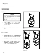


MANUAL MODE COMPONENT INSTALLATION (CONT'D)
8. If using a Single Jet nozzle proceed to step 13.
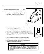
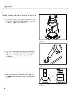
9. Using the Vacuum Pick Adjust Control on the handpiece, adjust the vacuum
cup to a point where the bottom of the vacuum cup touches the component
body. The component is now held in position with the vacuum cup.
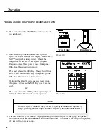
Figure 36.
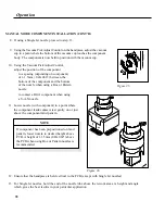
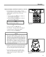
11. Lower nozzle (with component) to a point where
the component leads/contacts rest gently on or just
above the component land pattern.
NOTE
If component has been prepositioned on land
pattern, lower nozzle to desired height above
PCB. A height of 1-1.5mm (.040-.060") above
the PCB when using Box or Pattern nozzles is
recommended.
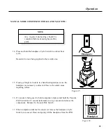
12. Ensure that the handpiece is held vertical to the PCB (except with Single Jet nozzles).
13. For Single Jet nozzles, hold the end of the nozzle tube above the rework area at a height and angle
which gives the best results in your particular application.
Figure 35.
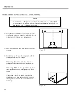
10. Using the Vacuum Pick Adjust Control,
adjust the position of the component
to a spacing (depending on component)
of 1-1.5mm (.040-.060”) between the
bottom of the component and the bottom
of the nozzle when using a Box or Pattern
nozzle.
to contact a BGA component when using
a V-A-N nozzle.
38
Operation
Содержание TF 200
Страница 1: ...OPERATION MAINTENANCE MANUAL PROGRAMMABLETHERMOFLO TF 500 TF 500E Systems TF 200 TF 200E Units ...
Страница 2: ...MANUAL NO 5050 0420 REV C i ...
Страница 26: ...21 Quick Start ...


