MST Construction Manual – Issue 1
Page 20
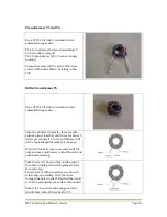
Transformers T1 and T4
Use a FT37-43 ferrite toroid and 0.5mm
enamelled copper wire.
T1: 4 turn primary (balanced modulator), 3
turn secondary (output)
T4: 10 turn primary (U1), 3 turn secondary
(output)
Scrape the enamel off the ends of the wires
and tin with solder before installing in the
PCB.
Bifilar transformer T5
Use a FT37-43 ferrite toroid and 0.25mm
enamelled copper wire.
Take two 300mm lengths lay them parallel
and then twist together until there are about 3
twists per centimetre. A vice and battery drill
with a hook shaped bit make this job easy.
Wind on 8 turns. Scrape some enamel off the
ends and use a multimeter to find the start and
end of each winding.
Take the start of one winding and the end of
the other winding and twist together to form
the centre tap.
Trim the leads with sidecutters and tin with
solder before installing. Push the wires
through the holes in the PCB and sit the toroid
so that it rests against the surface of the board.
Ensure the two-wire centre tap goes to the
middle hole in the PCB overlay for T5.
Содержание MST400
Страница 1: ...MST Construction Manual Issue 1 Page 1 MST CONSTRUCTION MANUAL ...
Страница 9: ...MST Construction Manual Issue 1 Page 9 Figure 2 SSB generator ...
Страница 10: ...MST Construction Manual Issue 1 Page 10 Figure 3 Transmit mixer ...
Страница 11: ...MST Construction Manual Issue 1 Page 11 Figure 4 Power amplifier ...
Страница 12: ...MST Construction Manual Issue 1 Page 12 Figure 5 Receive mixer ...
Страница 13: ...MST Construction Manual Issue 1 Page 13 Figure 6 Receive audio ...
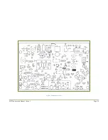
Страница 22: ...MST Construction Manual Issue 1 Page 22 Figure 7 Component overlay ...
Страница 25: ...MST Construction Manual Issue 1 Page 25 Figure 8 Front panel drilling guide ...


