background image

MST Construction Manual – Issue 1 

Page 29 


8


T

ESTING AND ALIGNMENT


8.1


G

ENERAL


A suggested list of basic tools and accessories to undertake testing is shown below.  


Digital multimeter. 


50 ohm dummy load capable of dissipating at least 5 Watts. 


QRP wattmeter or oscilloscope. 


Power supply capable of 13.8V DC at 2 Amps. 


Small adjustment screwdriver. 


An audio signal generator. 


An RF signal generator. 


A frequency counter. 

Obviously an external VFO is required for testing and operation and it is assumed during 
the rest of this section that the MST board is being used with the DDS VFO which is 
already configured and fully operational. 

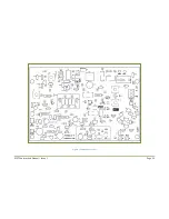
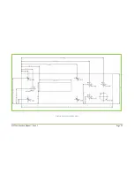
Figure 11 lists typical voltages at various points around the board and can be used to 
verify operation. 

8.2


P

OWER ON


Temporarily remove the power connector for the VFO so that the MST board current can 
be measured alone. 


Using a small screwdriver: 

o


 Rotate the bias trimpot VR2 fully ant-clockwise so that the gate bias voltage is 
zero volts. 

o


Set the trimmer capacitors to halfway. 

o


Set carrier balance trimpot VR1 to halfway by counting turns. You should hear a 
slight click as you reach the end. 


Connect the power supply to the board terminals. 

Double check the polarity is correct 

before applying power


If your power supply does not include a current meter, connect a multimeter in series 
with the power supply positive lead and set to measure current. 


 Connect a 50 Ohm dummy load to the antenna socket. 


Turn on the power supply and note the supply current. It should be around 70mA. If it’s 
far from this turn off immediately and look for problems. 


The relay should be de-energized and the board in receive mode. To verify that there are 
no obvious problems do a quick probe around the board with a multimeter and check 
the DC receive voltages as shown in Figure 11.  


Plug in the VFO power connector. Check the power supply current. If using the DDS VFO 
it should rise to around 150mA but this is highly dependent on the type of LCD used and 
the backlight current.  


Содержание MST400

Страница 1: ...MST Construction Manual Issue 1 Page 1 MST CONSTRUCTION MANUAL ...

Страница 2: ...st 14 4 1 Main Board Parts 14 4 2 Band Specific Parts 16 4 3 Off Board Parts 16 5 Construction 17 5 1 General 17 5 2 Construction Steps 17 6 Enclosure 23 6 1 Rear Panel 23 6 2 Front Panel 23 6 3 Mounting the PCB 23 6 4 Front panel label 24 6 5 Fitting the DDS VFO 26 7 Wiring up 27 8 Testing and alignment 29 8 1 General 29 8 2 Power on 29 8 3 Receive 30 8 4 Transmit 30 8 5 Carrier frequency adjustm...

Страница 3: ...re 3 Transmit mixer 10 Figure 4 Power amplifier 11 Figure 5 Receive mixer 12 Figure 6 Receive audio 13 Figure 7 Component overlay 22 Figure 8 Front panel drilling guide 25 Figure 9 DDS VFO front panel mounting 26 Figure 10 Wiring diagram 28 Figure 11 Typical circuit voltages 31 Figure 12 Crystal filter response 32 ...

Страница 4: ...lectable frequency steps and programmable IF offset MST Features 1 Complete SSB transceiver on a single PCB just add a VFO 2 Superhet receiver using a 4 pole 10MHz crystal filter 3 5W PEP minimum power output using a rugged power MOSFET output stage 4 Unwanted sideband suppression is typically 40dB 5 All spurious transmit outputs below 45dBc 6 AF and microphone gain controls 7 Easy to adjust and s...

Страница 5: ...MST Construction Manual Issue 1 Page 5 2 BLOCK DIAGRAM Figure 1 MST Block diagram Receive Path Transmit Path ...

Страница 6: ...ge the balance is upset and a double sideband suppressed carrier signal is produced at the output of T1 Note that capacitor C8 holds the junction of D1 and D2 at ground for RF Due to variations in component parameters the balance is not exact and so trimcap TC2 and trimpot VR1 are adjusted to bring the modulator into balance In practice up to 50dB of carrier suppression can be achieved Diode D5 is...

Страница 7: ...he waveform from Q7 can be high in harmonics and so a 5 pole low pass filter is included to reduce the level of harmonic and other spurious energy to an acceptable level The values of the low pass filter components are band dependant When the PTT is operated the transmit receive relay is energized and the filtered transmit signal is passed to the antenna When the PTT is not operated the relay swit...

Страница 8: ...high frequency response of U3 is limited by C35 and C42 while capacitors C37 and C36 reduce the low frequency response The output of U3 is fed to a 1uF coupling capacitor and 1K resistor R28 to the AF gain potentiometer When switching to transmit mode MOSFET Q5 is turned on rapidly through D9 charging C45 and shorting the audio line to ground When returning to receive mode Q5 slowly turns off as C...

Страница 9: ...MST Construction Manual Issue 1 Page 9 Figure 2 SSB generator ...

Страница 10: ...MST Construction Manual Issue 1 Page 10 Figure 3 Transmit mixer ...

Страница 11: ...MST Construction Manual Issue 1 Page 11 Figure 4 Power amplifier ...

Страница 12: ...MST Construction Manual Issue 1 Page 12 Figure 5 Receive mixer ...

Страница 13: ...MST Construction Manual Issue 1 Page 13 Figure 6 Receive audio ...

Страница 14: ...V polyester MKT C17 4 1uF 16V RB electrolytic C20 C43 C44 C45 2 10uF 16V RB electrolytic C18 C41 1 22uF 16V RB electrolytic C54 3 100uF 25V RB electrolytic C2 C32 C39 3 470uF 25V RB electrolytic C46 C48 C57 2 50pF ceramic trimcap 0 2 pitch TC1 TC2 See Text C1 4 10R 1 4W 1 resistor R27 R30 R34 R35 1 15R 1 4W 1 resistor R36 1 56R 1 4W 1 resistor R38 6 100R 1 4W 1 resistor R4 R6 R15 R17 R24 R43 1 220...

Страница 15: ...F mixer amp U1 U2 U5 1 NE5534 low noise op amp U3 1 LM386N 4 audio power amp U4 5 10MHz HC49 crystal X1 X2 X3 X4 X5 1 DPDT DIP relay 12V coil K1 1 FT37 43 4 turns 3 turns 0 5mm T1 4 42IF123 10 7MHz IF Transformer T2 T3 T7 T8 1 FT37 43 10 turns 3 turns 0 5mm T4 1 FT37 43 8 turns bifilar 0 25mm T5 1 BN 43 202 2 turns 5 turns 0 5mm T6 2 PCB pin 1mm P1 ANT P2 GND 6 2 pin 2 54mm pitch header SK1 MIC SK...

Страница 16: ...ent 1 Plastic instrument case 200mm x 155mm x 65mm with aluminium panels www altronics com au H0480F or equivalent 1 red binding post 1 black binding post 1 SO239 panel mount socket 3 knobs 2 10K log pot 16mm 1 5mm amber LED and bezel 1 microphone socket 1 front panel label 1 loudspeaker 8 ohm 67mm square or equivalent 4 4g x 6mm self tapping screws 8 3mm x 6mm screws 4 3mm x 10mm screws 4 3mm nut...

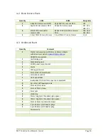
Страница 17: ...f components before installation There isn t a best scheme for loading the components If desired you can build sections at a time and test them out but it is not necessary and in any case some sections rely on others before they will operate The suggested procedure is to load the smaller components first and then work upwards 5 2 CONSTRUCTION STEPS Refer to the parts list and Figure 7when installi...

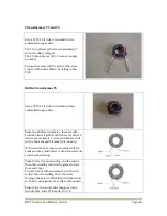
Страница 18: ... between pin 1 and pin 8 This is shown in the top view diagram below Double check they are installed in the correct orientation Step 7 Electrolytic capacitors These are polarized and must go in the correct way The component overlay has a mark to indicate the positive lead Step 8 Connectors There are a number of connectors fitted to the PCB to provide a neat finished product They also allow easy re...

Страница 19: ...e and down the other Starting at the opposite end wind the 5 turn secondary in the same manner Use 0 5mm enamelled copper wire The secondary is the output and connects to the LPF Scrape the enamel off the ends of the wires and tin with solder Check with a multimeter that there are no shorts between the windings before installing in the PCB Low Pass Filter Coils L1 and L2 Wind the turns shown below...

Страница 20: ...lay them parallel and then twist together until there are about 3 twists per centimetre A vice and battery drill with a hook shaped bit make this job easy Wind on 8 turns Scrape some enamel off the ends and use a multimeter to find the start and end of each winding Take the start of one winding and the end of the other winding and twist together to form the centre tap Trim the leads with sidecutte...

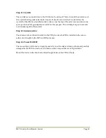
Страница 21: ...he PCB groundplane set aside for this purpose This will help keep out noise and resist widening of the filter skirts Step 12 Antenna wires The antenna wires are hard to solder to the PCB pins once the PCB is installed in the case so solder short lengths to the ANT and GND pins now Step 13 Power MOSFET The reason this is left to last is simply because it is near the edge and may get bent and possib...

Страница 22: ...MST Construction Manual Issue 1 Page 22 Figure 7 Component overlay ...

Страница 23: ...ble check connections with a multimeter 6 1 REAR PANEL The rear panel only contains the SO239 antenna socket and two binding post to connect the power supply As the rear panel layout is straightforward no layout drawing is supplied however remember to locate the antenna socket near the PCB pins so the wires are kept short 6 2 FRONT PANEL The front panel is designed to accommodate the DDS VFO It re...

Страница 24: ... knife and steel rule as a guide cut out the inside area of the LCD window Touch up any bare paper edges with a black permanent marker 3 Laminate the whole sheet using an A4 laminator If you don t have your own then this can be done quite cheaply at large stationary stores The exciting thing about this is that the LCD cutout becomes a transparent window 4 Using the hobby knife cutout the other hol...

Страница 25: ...MST Construction Manual Issue 1 Page 25 Figure 8 Front panel drilling guide ...

Страница 26: ... to provide a flush surface for the front panel label to sit If preferred round head screws can be used which means that holes need to be made in the label and also the heads will be visible from the front If a LCD is used that does not incorporate a backlight it will not be as high and so the length of the screws and spacers need to be reduced accordingly The general mounting arrangement is shown...

Страница 27: ...with long nose pliers to hold in place and then solder Be careful not to use too much heat and solder as it will make it difficult to insert the contact into the housing Not that the microphone socket PTT wires go directly to the PCB but the audio wires connect to the mic gain pot before going to the PCB The power supply connection uses a screw terminal block because of the higher currents employe...

Страница 28: ...MST Construction Manual Issue 1 Page 28 Loudspeaker Antenna 13 8V DC POS NEG Mic socket Mic gain AF gain PWR LED VFO OUT PWR Figure 10 Wiring diagram ...

Страница 29: ...trimpot VR2 fully ant clockwise so that the gate bias voltage is zero volts o Set the trimmer capacitors to halfway o Set carrier balance trimpot VR1 to halfway by counting turns You should hear a slight click as you reach the end Connect the power supply to the board terminals Double check the polarity is correct before applying power If your power supply does not include a current meter connect ...

Страница 30: ... the power supply current This is the quiescent transmit current and should be about 100mA higher than the receive current Anything far from this indicates a problem and should be investigated Operate the PTT and using a screwdriver slowly rotate the bias trimpot clockwise The power supply current should rise gradually and smoothly Keep increasing until the power supply current is 150mA higher tha...

Страница 31: ...3 pin 7 13 3V 0V U3 pin 6 6 7V 0V U4 pin 6 13 7V 0V U4 pin 5 6 7V 0V Q1 collector 9V 9V Q1 emitter 5 6V 5 6V Q2 emitter 0V 6V Q4 emitter 0V 7 2V Q3 collector 0V 8V U5 pin 8 0V 6 8V U5 pin 5 0V 5 6V Q9 emitter 0V 1 5V Q6 emitter 0V 1 5V Q7 gate 0V 3 9V Note readings taken with a power supply voltage of 13 8V DC Figure 11 Typical circuit voltages ...

Страница 32: ...arrier frequency may need adjusting There are a number of ways to go about this but the easiest is to listen to a good strength station of known quality while gently adjusting trimmer capacitor TC1 Adjust until the received audio sounds natural and the balance of high and low audio frequencies is correct Alternatively monitor yourself on a nearby receiver while speaking and adjust the carrier freq...

Страница 33: ... LM386 otherwise you will find audio peaks quite uncomfortable To transmit press the PTT button on your microphone and talk The front panel RF LED indicator will illuminate on voice peaks It can also be used as a rough guide to power output as the current through the LED and therefore its brightness is dependent on the peak RF output If the LED is illuminated at a constant level when talking it in...

Отзывы: