MST Construction Manual – Issue 1
Page 23
6
E
NCLOSURE
Now that your MST board is completed you’ll want to put it in an enclosure and try it out. The
PCB was designed to fit inside a plastic instrument enclosure 200mm wide by 155mm deep by
65mm high. A suitable type is catalogue number H0480F available from
www.altronics.com.au
.
It can be purchased with aluminium panels or you can easily make them yourself from 1.5 or
2mm thick aluminium sheet. The PCB mounting holes match plastic pillars on the bottom of the
enclosure and it will be necessary to remove unwanted pillars using either a large pair of
sidecutters or carefully with a large drill. Of course any other enclosure that accommodates the
PCB will be suitable, although if using the companion DDS VFO it will need to have similar
minimum dimensions.
Before installing the board in the enclosure, carefully look for errors, such as components in the
wrong way and solder bridges between tracks. The risk of solder bridges is greatly reduced due
to the solder mask, but check anyway. A few moments spent here is cheap insurance against big
problems later on.
One of the more common problems is poor solder joints with enamel covered wire. Some types
when soldered will melt the enamel but most will not, so it is important to remove the enamel
off the ends of the wires with sandpaper or a sharp knife before soldering. Double check
connections with a multimeter.
6.1
R
EAR
P
ANEL
The rear panel only contains the SO239 antenna socket and two binding post to connect the
power supply. As the rear panel layout is straightforward no layout drawing is supplied,
however remember to locate the antenna socket near the PCB pins so the wires are kept short.
6.2
F
RONT
P
ANEL
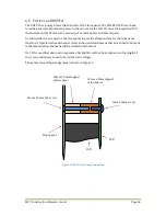
The front panel is designed to accommodate the DDS VFO. It requires a number of holes and cut-
outs to be made as shown in Figure 8. The microphone hole is dimensioned to fit a standard 4
pin connector however this may need changing to match your own.
There are two options for the VFO mounting holes. Make them countersink to have a flush
surface and no holes in the label, or if you are happy to have screw heads showing on the front
leave them straight drilled.
6.3
M
OUNTING THE
PCB
Temporarily put the rear panel in place and sit the PCB on the mounting pillars. If needed bend
the leads of Q7 slightly so that the metal tab is resting parallel against the rear panel. Use a
sharp pencil or scriber and run around the inside of the hole in the tab to mark the position for
the mounting hole on the rear panel. Remove the rear panel and drill a 3mm hole ensuring that
you remove all burrs.
Screw the PCB to the mounting pillars using small self tapping screws. Slide an insulating
washer between the rear panel and Q7 tab. Insert a plastic bush into Q7 tab then pass a 3mm
screw from the rear through the bush and screw on a nut and tighten. Check with a multimeter
that there is no electrical connection between the rear panel and Q7 tab.
Содержание MST400
Страница 1: ...MST Construction Manual Issue 1 Page 1 MST CONSTRUCTION MANUAL ...
Страница 9: ...MST Construction Manual Issue 1 Page 9 Figure 2 SSB generator ...
Страница 10: ...MST Construction Manual Issue 1 Page 10 Figure 3 Transmit mixer ...
Страница 11: ...MST Construction Manual Issue 1 Page 11 Figure 4 Power amplifier ...
Страница 12: ...MST Construction Manual Issue 1 Page 12 Figure 5 Receive mixer ...
Страница 13: ...MST Construction Manual Issue 1 Page 13 Figure 6 Receive audio ...
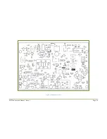
Страница 22: ...MST Construction Manual Issue 1 Page 22 Figure 7 Component overlay ...
Страница 25: ...MST Construction Manual Issue 1 Page 25 Figure 8 Front panel drilling guide ...


