MST Construction Manual – Issue 1
Page 19
Step 10: Coils
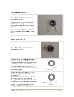
Output transformer T6
T6 is wound on a 13mm two hole
ferrite balun former type BN-43-202.
The edges of the holes are quite sharp
and can scrape the enamel off the
wires. To reduce scraping and the risk
of shorts, cut two lengths of 3mm heat
shrink and feed into the balun former
holes.
Wind the 2 turn primary with 0.5mm
enamelled copper wire. The primary
winding connects to Q7 drain. A turn is
where the wire passes up through one
hole and down the other.
Starting at the opposite end wind the 5
turn secondary in the same manner.
Use 0.5mm enamelled copper wire.
The secondary is the output and
connects to the LPF.
Scrape the enamel off the ends of the
wires and tin with solder. Check with a
multimeter that there are no shorts
between the windings before installing
in the PCB.
Low Pass Filter Coils L1 and L2
Wind the turns shown below for the required
band using 0.5mm enamelled copper wire on a
T50-2 toroid.
40M: 15 turns. 80M: 21 turns
Note the direction of winding as this makes for
a neater alignment of the toroid in the PCB.
Scrape the enamel off the ends of the wires
and tin with solder before installing in the
PCB.
Содержание MST400
Страница 1: ...MST Construction Manual Issue 1 Page 1 MST CONSTRUCTION MANUAL ...
Страница 9: ...MST Construction Manual Issue 1 Page 9 Figure 2 SSB generator ...
Страница 10: ...MST Construction Manual Issue 1 Page 10 Figure 3 Transmit mixer ...
Страница 11: ...MST Construction Manual Issue 1 Page 11 Figure 4 Power amplifier ...
Страница 12: ...MST Construction Manual Issue 1 Page 12 Figure 5 Receive mixer ...
Страница 13: ...MST Construction Manual Issue 1 Page 13 Figure 6 Receive audio ...
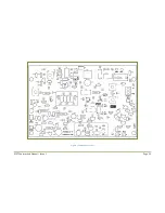
Страница 22: ...MST Construction Manual Issue 1 Page 22 Figure 7 Component overlay ...
Страница 25: ...MST Construction Manual Issue 1 Page 25 Figure 8 Front panel drilling guide ...


