background image


VZR.235900.000 IG


Cube С-04 Turnstile 

Installation Guidelines 


14 

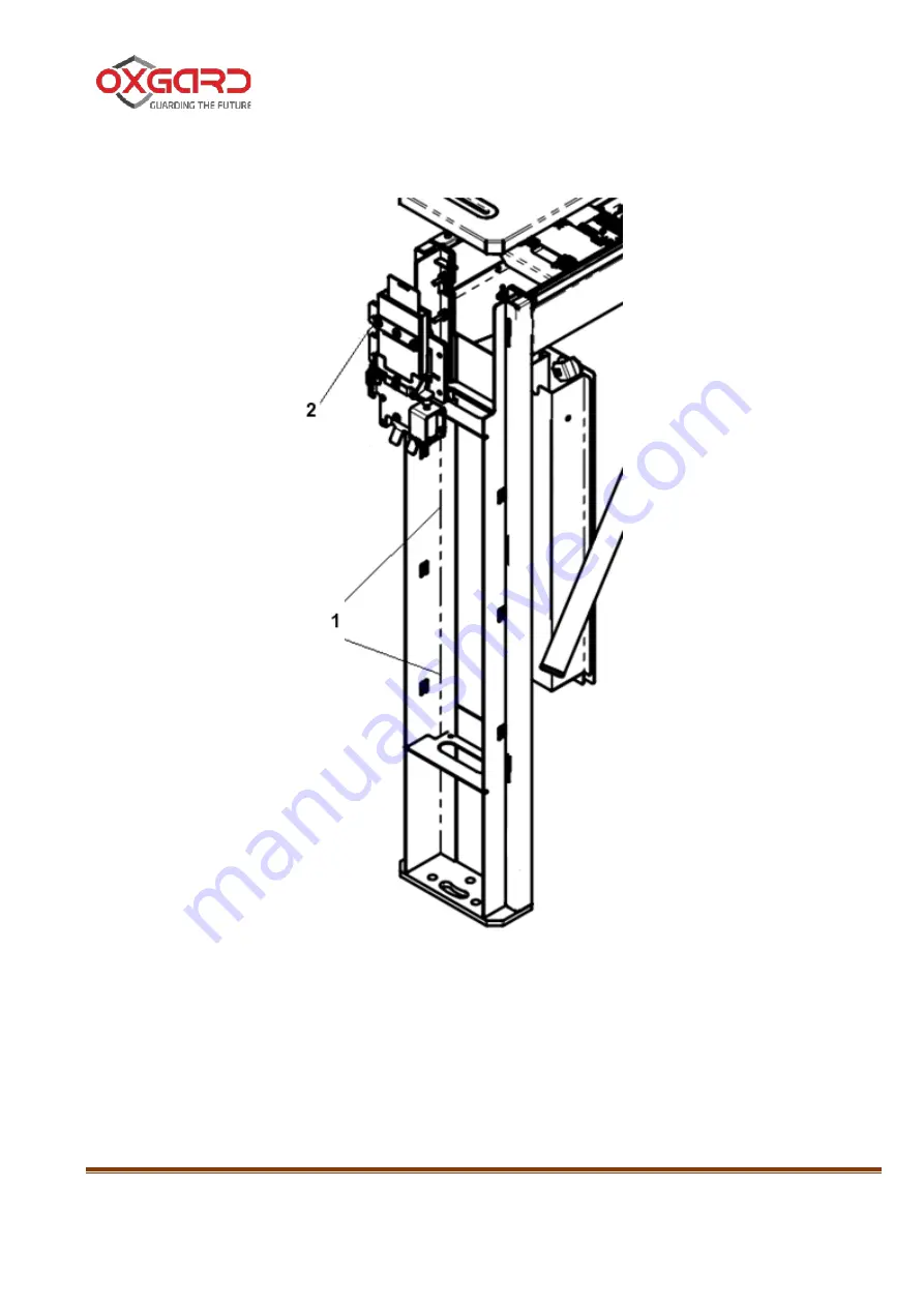
Figure 7 - routing of cables (1) is indicated with dashed lines, the cable input 

hole under the top cover (2). 


Figure 7 – Routing of control and power supply cables 


1 -  cable routing locations; 
2 – cable input hole 

Содержание CUBE ?-04 Series

Страница 1: ...ROZHDENIE LLC OKPD 2 26 30 50 110 TU 26 30 50 007 33120038 2017 APPROVED VZR 235900 000 LU TURNSTILE MODEL CUBE 04 04 c 04 04 c 04 H 04 Hc 04 04 c VZR 235900 000 IG INSTALLATION GUIDELINES Sheets 40 2...

Страница 2: ...ng the Product 11 4 3 Dismounting the product 15 5 ConnectiNG and AdjustING THE PRODUCT 16 5 1 Power supply connection 19 5 2 Control Panel Connection 19 5 3 Connecting Access Monitoring and Control S...

Страница 3: ...sonnel should additionally read Operational Manual VZR 235900 000 OM Due to continuous work on the improvement of the product its design might be subject to changes that have not been reflected in thi...

Страница 4: ...ll safety reasons Prior to starting the installation works fully de energize the product DO NOT INSTALL THE POWER SUPPLY UNIT INSIDE THE TURNSTILE CASING BECAUSE THIS MAY CAUSE ELECTROCUTION INSTALL T...

Страница 5: ...ng with electrical installations of up to 1000V shall be permitted to install the product ATTENTION FAILURE TO COMPLY WITH SAFETY REQUIREMENTS SPECIFIED IN THIS SECTION MAY CAUSE DAMAGE TO HUMAN LIFE...

Страница 6: ...o temperature the product shall be kept in a room under normal climatic conditions during 12 hours to avoid moisture condensation When carrying out handling operations safety requirements shall be obs...

Страница 7: ...ation Guidelines 7 3 3 2 Inspect the product externally The product shall have no visible damages 3 3 3 Should any damages be revealed prepare a Damage Claim 3 3 4 Figure 1 Turnstile s overall dimensi...

Страница 8: ...NG IN THE COURSE OF OPERATION INSTALL IT SECURELY IN CASE OF TURNSTILE INSTALLATION ON LOW STRENGTH FLOOR TAKE MEASURES TO FLOOR STRENGTHENING ON INSTALLATION SITE Figure 2 During the installation of...

Страница 9: ...SHALL BE PROVIDED TO ALLOW RECORDING OF PASSAGES DURING TURNSTILE OPERATION UNDER AMCS CONTROL AND TO AVOID UNAUTHORIZED PASSAGES 3 5 1 Figure 3 Arrangement of turnstile s passage zone and instruction...

Страница 10: ...nt The equipment used during turnstile installation 1 electric puncher 2 10mm dia solid carbide drill for drilling holes in the floor for anchors recommended anchor with screw type FH 10 10 SK 3 Allen...

Страница 11: ...NTING THE PRODUCT Figure 4 Turnstile s main panels Figure 4 to access all required turnstile assemblies the turnstile should be partially disassembled dismounting of the card collector containers 1 th...

Страница 12: ...nd SAFAS connection location 4 2 3 Turnstile s installation site Figure 5 prepare 6 holes 11 mm diameter in the floor for two turnstile stand anchors Figure 5 Turnstile stands The layout of mounting h...

Страница 13: ...plate of the turnstile stands 4 2 5 Route the RC panel s cable PSU s cable and where provided AMCS and SAFAS cables in the cable conduit or cable channel 4 2 6 Install the turnstile on the prepared pl...

Страница 14: ...tile Installation Guidelines 14 Figure 7 routing of cables 1 is indicated with dashed lines the cable input hole under the top cover 2 Figure 7 Routing of control and power supply cables 1 cable routi...

Страница 15: ...of 10 mm Figure 4 Install the side 2 and top 3 covers the turnstile card collector containers 1 4 2 9 Remove the protective film from the turnstile housing 4 3 Dismounting the product 4 3 1 Dismounti...

Страница 16: ...gram PSU RC panel and AMCS shall be connected using the motherboard Figure 8 Layout of boards under top cover on turnstile stand Figure 8 Layout of boards under top cover 1 Display Control Board 2 Car...

Страница 17: ...ired contacts the top cover shall be removed To do that use the key to open an remove the both containers located inside the turnstile stand then release 4 mounting studs of the top cover Figure 9 1 a...

Страница 18: ...ions of jumpers on the mainboard are detailed in Table 1 Table 1 Turnstile s mode of operation Jumper positions Turnstile s mode of operation Potential Mode 1 On position Potential Mode p 5 3 1 OFF po...

Страница 19: ...he turnstile is powered by a 12 VDC unit Max consumption 3 0 A PSU shall be selected based on these parameters Also it should be considered that when increasing the feeder cable length the voltage dro...

Страница 20: ...pose of AMCS contacts Labeling of contacts Purpose of contacts LEFT RIGHT left right single passage lowest priority STOP no passage is allowed Stop mode highest priority GND common contact Inputs for...

Страница 21: ...that has been on before AMCS operation LEFT and RIGHT inputs can operate both in potential and pulse mode actuation based on the evidence of closing to GND contact The pulse mode is set by default For...

Страница 22: ...y contact principle Okl and Ok2 are implemented in the motherboard NO and COMM normally open connection NC and COMM normally closed connection Actuation of one of the group of contacts indicates perfo...

Страница 23: ...barrier arms When in correct location D12 and D13 are not illuminated 5 4 Connecting control panel to AMCS controller In some cases the RC panel of the turnstile shall be connected directly to AMCS c...

Страница 24: ...ons Table 4 Purpose of OUT group of contacts Labeling of contacts Purpose of contacts OUT1 Left button status 1 OUT2 Right button status 3 OUT3 Stop button status 2 Outputs OUT1 OUT3 reflect current s...

Страница 25: ...puts OUT1 OUT3 can be connected both to AMCS controller directly and via the relay Figure 13 when using the relay the diode connection in parallel to winding IS OBLIGATORY Figure 13 Wiring diagram for...

Страница 26: ...nd STOP contacts The essential feature of RC panel connection via AMCS controller is the impossibility for using the turnstile modes that are set by means of the panel s button combinations except the...

Страница 27: ...ners with locks for fast access to withdrawn cards as well as for access to the top cover fixing screws The card collector board is located under the turnstile s top cover Remove the top cover to conn...

Страница 28: ...card collector board Make sure the cable is secure 5 5 2 Actuation device connection Figure 15 The actuation device AD is connected to the card collector using two groups of contacts the output signal...

Страница 29: ...with the use of card collector are given in Appendix D Figure 15 AMCS controller connection to the card collector is carried out by means of three groups of contacts Take Card GND Free Pass GND and Ca...

Страница 30: ...al for AD by means of group of contacts Let Go At that the side display panel illuminates green light The Cardcollector Free Pass Input can operate both in potential and in pulse mode actuation by the...

Страница 31: ...31 NC NO and COMM contacts The relay output operating by dry contact principle which closes opens for 1 second transmitting the card withdrawal confirmation signal to AMCS controller NC and COMM norm...

Страница 32: ...readiness for use 6 1 1 Check that the turnstile s parts and assemblies are tightly fastened 6 1 2 Make sure all cables are secure 6 1 3 Switch on the turnstile s power supply and check for serviceabi...

Страница 33: ...the representative of the installing organization demonstrates that the product is secure 2 records on the product installation are made into Datasheet VZR 235900 000 DS in the Section Product Histor...

Страница 34: ...nces above 25 m using of Cat5e or Cat6 twisted pair is obligatory The total DC resistance of the RC panel power supply wire shall not exceed 50 In case this requirement fails to be met where the panel...

Страница 35: ...nes 35 APPENDIX B LAYOUT OF MOUNTING HOLES IN RELATION TO TURNSTILE EXTERNAL DIMENSIONS Figure 16 Layout of mounting holes in relation to turnstile external dimensions Figure 16 Layout of mounting hol...

Страница 36: ...VZR 235900 000 IG Cube 04 Turnstile Installation Guidelines 36 APPENDIX C TURNSTILE CONNECTION DIAGRAM Figure 17 Turnstile Connection Diagram...

Страница 37: ...ctor properly can control the actuating device therefore 1 and 2 links are drawn as dashed lines This Diagram feature two available readers It is necessary to install the second reader outside the car...

Страница 38: ...rallel connection of several AMCS controllers to one reader AMCS controllers are connected to different card collector inputs Data on permanent keys is contained in the memory of one of controllers th...

Страница 39: ...l progressing reduces the cost of the system being installed A controller with two output signals to one reader input is used for that purpose the controller can differentiate the visitor and the perm...

Страница 40: ...ie LLC 66 Sofijskaya Str Saint Petersburg 192289 Telephone Fax 7 812 366 15 94 www oxgard com info oxgard com Import and Service VZR System OU Tulika tn 19 Tallinn 372 5844 4957 7 921 996 2746 info vz...

Отзывы: