background image

5.Advanced User Guidebook


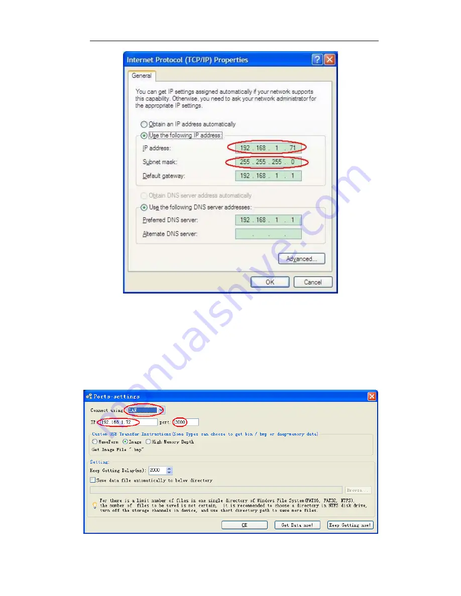
Figure 5-50 Set the network parameters of the computer 

(3) 

Set the network parameters of the OWON Oscilloscope Software. 

Run the 

software on the computer, choose the "Ports-settings" of the "Communications" 
menu item. Set "Connect using" to LAN. About the IP, the first three bytes is 
same as the IP in the step (2), the last byte should be different. Here, we set it to 
192.168.1.72. The range of the port value is 0

4000, but the port which under 

2000 is always be used, so it is suggested to set it to the value above 2000. Here, 
we set it to 3000. 


Figure 5-51 Set the network parameters of the OWON Oscilloscope Software 


61

Содержание SDS series

Страница 1: ...l Storage Oscilloscopes User Manual SDS6062 V SDS7102 V SDS8102 V SDS8202 V SDS8302 SDS9302 Note V for VGA interface optional SDS8302 and SDS9302 including VGA interface as default WWW OWON COM WWW OWON COM HK WWW OWON COM CN ...

Страница 2: ...inue to improve products and reserves the rights to changes specification at any time without notice OWON is the registered trademark of the Lilliput Company Headquarter Fujian Lilliput Optoelectronics Technology Co Ltd The mansion of optoelectronics 19 Heming Road Lantian industrial zone Zhangzhou Fujian China Tel 86 596 2130430 Fax 86 596 2109272 Web www owon com hk Mail Business Consulting sale...

Страница 3: ...chase This warranty shall not apply to any defect failure or damage caused by improper use or improper or inadequate maintenance and care Lilliput shall not be obligated to furnish service under this warranty a to repair damage resulting from attempts by personnel other than Lilliput representatives to install repair or service the product b to repair damage resulting from improper use or connecti...

Страница 4: ...Use the Probe Safely 15 How to Implement Self calibration 15 Introduction to the Vertical System 16 Introduction to the Horizontal System 17 Introduction to the Trigger System 18 5 Advanced User Guidebook 19 How to Set the Vertical System 20 Use Mathematical Manipulation Function 26 Using FFT function 27 Use VERTICAL POSITION and VOLTS DIV Knobs 31 How to Set the Horizontal System 32 How to Set th...

Страница 5: ...Example 2 Gain of a Amplifier in a Metering Circuit 78 Example 3 Capturing a Single Signal 79 Example 4 Analyze the Details of a Signal 81 Example 5 Application of X Y Function 82 Example 6 Video Signal Trigger 84 7 Troubleshooting 85 8 Technical Specifications 86 General Technical Specifications 91 9 Appendix 92 Appendix A Enclosure 92 Appendix B General Care and Cleaning 92 Appendix C Battery Us...

Страница 6: ...tput terminal When powered by AC power it is not allowed to measure AC power source directly because the testing ground and power cord ground conductor are connected together otherwise it will cause short circuit When powered by battery the product must ground connection To avoid electric shock there must be a ground wire connect between ground and the ground port on the back of product panel Chec...

Страница 7: ... accessible potentially Caution It indicates a potential damage to the instrument or other property might occur Safety Symbols Symbols on the product The following symbol may appear on the product Hazardous Voltage Refer to Manual Protective Earth Terminal Chassis Ground Test Ground To avoid body damage and prevent product and connected equipment damage carefully read the following safety informat...

Страница 8: ...n the battery powered oscilloscope is connected to the AC powered PC through the ports Warning To avoid fire or electrical shock when the oscilloscope input signal connected is more than 42V peak 30Vrms or on circuits of more than 4800VA please take note of below items z Only use accessory insulated voltage probes and test lead z Check the accessories such as probe before use and replace it if the...

Страница 9: ...n 7cm smart design body 8 inch high definition TFT display 800 x 600 pixels Built in FFT function Pass Fail Function Waveform record and playback VGA interface only for the model with V or the models including VGA interface as default Various triggering function USB communication ports Super capacity lithium battery Optional Built in Chinese and English help system Multiple language support 4 ...

Страница 10: ...the user interface z How to implement the general inspection z How to implement the function inspection z How to make a probe compensation z How to set the probe attenuation coefficient z How to use the probe safely z How to implement an auto calibration z Introduction to the vertical system z Introduction to the horizontal system z Introduction to the trigger system 5 ...

Страница 11: ...nction pushbuttons are included The knobs have the functions similar to other oscilloscopes The 5 buttons F1 F5 in the column on the right side of the display screen or in the row under the display screen H1 H5 are menu selection buttons through which you can set the different options for the current menu The other pushbuttons are function buttons through which you can enter different function men...

Страница 12: ... Power switch represents power ON represents power OFF 2 AC power input jack Right Side Panel Figure 4 3 Right side panel 1 USB Host port It is used to transfer data when external USB equipment connects to the oscilloscope regarded as host device For example upgrading software by USB flash disk needs to use this port 2 USB Device port It is used to transfer data when external USB equipment connect...

Страница 13: ...ith external equipment as serial port or to connect the oscilloscope with a monitor or a projector as VGA output for the model with V 4 LAN port the network port which can be used to connect with PC Rear Panel Figure 4 4 Rear Panel 1 The port of trigger signal output Pass Fail output 2 Handle 3 Air vents 4 Foot stool which can adjust the tilt angle of the oscilloscope 5 Ground connection 8 ...

Страница 14: ...U and CH2 MENU correspond to setting menu in CH1 and CH2 Math key refer to math menu the math menu consists of six kinds of operations including CH1 CH2 CH2 CH1 CH1 CH2 CH1 CH2 CH1 CH2 and FFT Two VERTICAL POSITION knob control the vertical position of CH1 CH2 and two VOLTS DIV knob control voltage scale of CH1 CH2 7 Horizontal control area with 1 key and 2 knobs HORIZONTAL POSITION knob control t...

Страница 15: ...y Stop Data acquisition stopped 3 The purple T pointer indicates the horizontal position for the trigger 4 The pointer indicates the trigger position in the internal memory 5 The two yellow dotted lines indicate the size of the viewing expanded window 6 It shows present triggering value and displays the site of present window in internal memory 7 It shows setting time see Config on P55 8 It indica...

Страница 16: ...a the maximum amplitude value Mi the minimum amplitude value Vt the Voltage value of the waveform s flat top value Vb the Voltage value of the waveform s flat base Va the amplitude value Os the overshoot value Ps the Preshoot value RT the rise time value FT the fall time value PW the width value NW the Width value D the Duty value D the Duty value PD the Delay A B value and ND the Delay A B value ...

Страница 17: ...ce test please get in touch with the Lilliput s distributor responsible for this business or the Lilliput s local offices If there is damage to the instrument caused by the transportation please keep the package With the transportation department or the Lilliput s distributor responsible for this business informed about it a repairing or replacement of the instrument will be arranged by the Lillip...

Страница 18: ...viation will result in the measuring error or mistake For adjusting the probe compensation please carry out the following steps 1 Set the attenuation coefficient of the probe in the menu as 10X and that of the switch in the probe as 10X see How to Set the Probe Attenuation Coefficient on P14 and connect the probe with the CH1 channel If a probe hook tip is used ensure that it keeps in close touch ...

Страница 19: ...splay the Probe menu select the proper value corresponding lid all the time before it is changed again factor of the oscilloscope To change or check the prob 1 Press the function menu button of the used channels CH1 MENU or C MENU 2 Press H3 bu to the probe This setting will be va Caution The default attenuation coefficient of the probe on the instrument is preset to re that the set value of the a...

Страница 20: ...tect you from suffering from the electric shock do not touch any metal part of the probe tip when it is connected to the power supply Before making any measurements always connect the probe to the instrument and connect the ground terminal to the earth How to Implement Self calibration The self calibration application can make the oscilloscope reach the optimum condition rapidly to obtain the most...

Страница 21: ...form Measuring Skill If the channel is under the DC coupling mode you can rapidly measure the DC component of the signal through the observation of the difference between the wave form and the signal ground If the channel is under the AC mode the DC component would be filtered out This mode helps you display the AC component of the signal with a higher sensitivity Vertical offset back to 0 shortcu...

Страница 22: ...e setting and observe the consequent status information change Rotate the horizontal SEC DIV knob to change the horizontal time base and it can be found that the Horizontal Time Base display in the status bar changes accordingly 2 Use the HORIZONTAL POSITION knob to adjust the horizontal position of the signal in the waveform window The HORIZONTAL POSITION knob is used to control the triggering di...

Страница 23: ... the TRIG LEVEL knob to change the trigger level setting By rotating the TRIG LEVEL knob the trigger indicator in the screen will move up and down With the movement of the trigger indicator it can be observed that the trigger level value displayed in the screen changes accordingly PS Turning the TRIG LEVEL knob can change trigger level value and it is also the hotkey to set trigger level back to 0...

Страница 24: ...f Chapter 4 Junior User Guidebook This chapter will deal with the following topics mainly z How to Set the Vertical System z How to Set the Horizontal System z How to Set the Trigger System z How to Implement the Sampling Setup z How to Set the Display System z How to Save and Recall Waveform z How to Record Playback Waveforms z How to Implement the Auxiliary System Function Setting z How to Imple...

Страница 25: ...ased on the channel To turn waveforms on or off channel math Pressing the CH1 MENU CH2 MENU or Math buttons have the following effect If the waveform is off the waveform is turned on and its menu is displayed If the waveform is on and its menu is not displayed its menu will be displayed If the waveform is on and its menu is displayed the waveform is turned off and its menu goes away CH1 menu CH2 m...

Страница 26: ...ts ratio Amps Volts ratio 1 Resistor value Volts Amp ratio is automatically calculated Limit SDS6062 V does not have this function full band 20M Get full bandwidth Limit the channel bandwidth to 20MHz to reduce display noise 1 To set channel coupling Taking the Channel 1 for example the measured signal is a square wave signal containing the direct current bias The operation steps are shown as belo...

Страница 27: ...ent settings in the operating menu of the Channel should always match what is on the probe see How to Set the Probe Attenuation Coefficient on P14 If the attenuation coefficient of the probe is 1 1 the menu setting of the input channel should be set to X1 Take the Channel 1 as an example the attenuation coefficient of the probe is 10 1 the operation steps are shown as follows 22 ...

Страница 28: ...robe Corresponding Menu Setting 1 1 X1 10 1 X10 100 1 X100 1000 1 X1000 3 To measure current by probing the voltage drop across a resistor Take the Channel 1 as an example if you are measuring current by probing the voltage drop across a 1Ω resistor the operation steps are shown as follows 1 Press the CH1 MENU button to show CH1 SETUP menu 2 Press the H3 menu selection the Probe menu will display ...

Страница 29: ...e Channel 1 for example the operation steps are shown as follows 1 Press the CH1 MENU button to show CH1 SETUP menu 2 Press the H2 menu selection button and select ON for Inverted item The waveform is inverted as it is shown in Figure 5 7 3 Press the H2 menu selection button again and select OFF for Inverted item The waveform goes back to its original one as it is shown in Figure 5 6 24 ...

Страница 30: ...unction When high frequency components of a waveform are not important to its analysis the bandwidth limit control can be used to reject frequencies above 20 MHz Taking the Channel 1 for example the operation steps are shown as below 1 Press the CH1 MENU button to show CH1 SETUP menu 2 Press the H4 button and the Limit menu will display 25 ...

Страница 31: ...addition multiplication division and subtraction operations between Channel 1 and Channel 2 and the FFT operation of Channel 1 or Channel 2 Figure 5 8 Wave math menu The corresponding FCL Functional Capabilities List of the Waveform Calculation Function Menu Setting Description Factor1 CH1 CH2 Select the signal source of the factor1 Sign Select the sign of mathematical manipulation Dual Wfm Math F...

Страница 32: ...t of the screen 3 Press the F1 menu selection button and choose CH1 for Factor1 4 Press the F2 menu selection button and choose 5 Press the F3 menu selection button and choose CH2 for Factor2 The green calculated waveform M is displayed in the screen Figure 5 9 Waveform resulted from CH1 CH2 Using FFT function The FFT fast Fourier transform math function mathematically converts a time domain wavef...

Страница 33: ...lect the FFT window There are four FFT windows Each one has trade offs between frequency resolution and magnitude accuracy What you want to measure and your source signal characteristics help you to determine which window to use Use the following guidelines to select the best window Type Characteristics Window Rectangle Best solution for frequency worst for magnitude Best type for measuring the fr...

Страница 34: ...gnal levels before and after the event are significantly different Blackman Best solution for magnitude worst for frequency Recommend to use for z Single frequency waveforms to find higher order harmonics Figure 5 10 Figure 5 11 Figure 5 12 Figure 5 13 are examples for measuring sine wave with a frequency of 1kHz under the selection of four different windows for FFT Figure 5 10 Rectangle window 29...

Страница 35: ...5 Advanced User Guidebook Figure 5 11 Hamming window Figure 5 12 Hanning window 30 ...

Страница 36: ...nts set the oscilloscope acquisition mode to average What is Nyquist frequency The Nyquist frequency is the highest frequency that any real time digitizing oscilloscope can acquire without aliasing This frequency is half of the sample rate Frequencies above the Nyquist frequency will be under sampled which causes aliasing So pay more attention to the relation between the frequency being sampled an...

Страница 37: ...creen see Figure 5 14 Figure 5 14 Information about Vertical Position How to Set the Horizontal System The HORIZONTAL CONTROLS includes the HORIZ MENU button and such knobs as HORIZONTAL POSITION and SEC DIV 1 HORIZONTAL POSITION knob this knob is used to adjust the horizontal positions of all channels include those obtained from the mathematical manipulation the analytic resolution of which chang...

Страница 38: ...ull screen Main Time Base Press the H1 menu selection button and choose Main In this case the HORIZONTAL POSITION and SEC DIV knobs are used to adjust the main window The display in the screen is shown as Figure 5 16 Figure 5 16 Main Time Base Set Window Press the H2 menu selection button and choose Set The screen will show a window area defined by two cursors Use the HORIZONTAL POSITION and SEC D...

Страница 39: ...igure 5 17 Window Setting Window Expansion Press the H3 menu selection button and choose Zoom As a result the window area defined by two cursors will be expanded to the full screen size see Figure 5 18 Figure 5 18 Zoom Window 34 ...

Страница 40: ... and Single mode Trigger Menu The button that activates the trigger control menu Trigger Control The oscilloscope provides two trigger types single trigger and alternate trigger Single trigger Use a trigger level to capture stable waveforms in two channels simultaneously Alternate trigger Trigger on non synchronized signals The Single Trigger and Alternate Trigger menus are described respectively ...

Страница 41: ...rrent component Allow all component pass Block the high frequency signal only low frequency component pass Block the low frequency signal only high frequency component pass Slope Trigger on rising edge Trigger on falling edge Mode Holdoff Auto Normal Single Holdoff Reset Acquire waveform even no trigger occurs Acquire waveform when trigger occurs When trigger occurs acquire one waveform then stop ...

Страница 42: ...filed Synchronic trigger in video even field Synchronic trigger in designed video line turn the M knob to set the line number Mode Holdoff Auto Holdoff Reset Acquire waveform even no trigger occurred 100ns 10s adjust the M knob to set time interval before another trigger occur Set Holdoff time as 100ns 3 Slope Trigger Slope trigger sets the oscilloscope as the positive negative slope trigger withi...

Страница 43: ...gger Pulse trigger occurs according to the width of pulse The abnormal signals can be detected through setting up the pulse width condition The Pulse Width Trigger Menu is shown as Figure 5 22 Figure 5 22 Pulse Width Trigger menu Pulse Width Trigger menu list MENU SETTING INSTRUCTION Single Mode Pulse Set vertical channel trigger type as pulse trigger Source CH1 CH2 Select CH1 as the trigger sourc...

Страница 44: ...lternate trigger Trigger Type Edge Menu is shown as Figure 5 23 Figure 5 23 Alternate trigger Trigger Type Edge Menu Alternate trigger Trigger Type Edge Menu list MENU SETTING INSTRUCTION Alternate Mode Edge Set vertical channel trigger type as edge trigger Source CH1 CH2 Select CH1 as the trigger source Select CH2 as the trigger source Couple AC DC HF LF Not allow DC portion to pass Allow all por...

Страница 45: ... in video odd filed Synchronic trigger in video even field Synchronic trigger in designed video line turn the M knob to set the line number Mode Holdoff Auto Holdoff Reset Acquire waveform even no trigger occurred 100ns 10s adjust the M knob to set time interval before another trigger occur Set Holdoff time as 100ns 3 Alternate trigger Trigger Mode Slope Alternate trigger Trigger Type Slope Menu i...

Страница 46: ... vertical channel trigger type as pulse trigger Source CH1 CH2 Select CH1 as the trigger source Select CH2 as the trigger source Coupling AC DC HF LF Not allow DC portion to pass Allow all portion pass Not allow high frequency of signal pass and only low frequency portion pass Not allow low frequency of signal pass and only high frequency portion pass Polarity Choose the polarity when Select pulse...

Страница 47: ...igger condition occurs while the oscilloscope is waiting for a specific period as determined by the time base setting it will force itself to trigger z Normal The Normal mode allows the oscilloscope to acquire a waveform only when it is triggered If no trigger occurs the oscilloscope keeps waiting and the previous waveform if any will remain on the display Single In Single mode after pressing the ...

Страница 48: ...displayed in the screen shown as Figure 5 27 Figure 5 27 ACQU MODE Menu The description of the Acqu Mode Menu is shown as follows Function Menu Setting Description Sample Normal sampling mode Peak detect Use to capture maximal and minimal samples Finding highest and lowest points over adjacent intervals It is used for the detection of the jamming burr and the possibility of reducing the confusion ...

Страница 49: ...K 1M Length 10M Choose the record length Change the ACQU Mode settings and observe the consequent variation of the wave form displayed Figure 5 28 Peak Detect mode under which the burrs on the falling edge of the square wave can be detected and the noise is heavy Figure 5 29 Normal ACQU Mode display in which no burr can be detected 44 ...

Страница 50: ...s f Description Type Vect nts in the display is filled with the vector form Dots Only the sampling points are displayed The space between the adjacent sampling poi Time 5 seconds nity Turn the M knob to set the persistence time OFF 1 second 2 seconds Infi Persist Clear Clear the persistence XY Mode nction ON OFF Turn on the XY display function Turn off the XY display fu Cymometer OFF ON Turn on th...

Страница 51: ...d Figure 5 33 Figure 5 32 Display in the Vector Form Figure 5 33 Display in Dots form Persist When the Persist function is used the persistence display effect of the picture tube oscilloscope can be simulated The reserved original data is displayed in fade color and the new data is in bright color Press the H2 button the Persist menu will display at the right of screen Press the F1 button differen...

Страница 52: ...ted Channel 1 is displayed in the horizontal axis and Channel 2 in the vertical axis the oscilloscope is set in the un triggered sample mode the data are displayed as bright spots The operations of all control knobs are as follows The Vertical VOLTS DIV and the VERTICAL POSITION knobs of Channel 1 are used to set the horizontal scale and position The Vertical VOLTS DIV and the VERTICAL POSITION kn...

Страница 53: ...s a one channel cymometer and it can only measure the frequency of the triggering channel In the ALT trigger mode it is a two channel cymometer and it can measure the frequency of two channels The cymometer is displayed at the right bottom of the screen To turn the cymometer on or off 1 Press the Display button 2 In the Display menu press the H4 button to toggle between the cymometer display ON or...

Страница 54: ...ll or close the waveform stored in the current object address When the show is ON if the current object address has been used the stored waveform will be shown the address number and relevant information will be displayed at the top left of the screen if the address is empty it will prompt None is saved Save Save the waveform of the source to the selected address Whatever the Type of save menu is ...

Страница 55: ...veform called out can not be adjusted In order to save the waveform of the CH1 into the address 1 the operation steps should be followed 1 Saving Press the H1 button the Type menu will display at the left of screen turn the M knob to choose Wave for Type 2 Press the H2 button and press F1 button to select CH1 for Source 3 Press the H3 button and press the F1 turn the M knob to select 1 as object a...

Страница 56: ... of the screen the USB disk is installed successfully The supported format of the USB disk FAT32 file system cluster size cannot exceed 4K Once the USB disk cannot be recognized you could format it into the supported format and try again 2 After the USB disk is installed press the Save panel button the save menu is displayed at the bottom of the screen 3 Press the H1 button the Type menu will disp...

Страница 57: ...ord wave according to the interval until it reaches the end frame set Record menu shows as follows Menu Setting Instruction Mode OFF Record Playback Storage Close wave record function Set record menu Set playback menu Set storage menu End frame Turn the M knob to select the number of frames to record 1 1000 Record mode FrameSet Interval Turn the M knob to select the interval between recorded frame...

Страница 58: ... the M knob to select the number of start frame to playback 1 1000 Turn the M knob to select the number of end frame to playback 1 1000 Turn the M knob to select the number of current frame to playback 1 1000 Turn the M knob to select the interval between played back frames 1ms 1000s Play mode Loop Once Play back the wave continuously Play back the wave just one time Operate Play Stop Begin to rec...

Страница 59: ...s follows Menu Setting Instruction Start frame Turn the M knob to select the number of start frame to store 1 1000 Storage Mode Frame Set End frame Turn the M knob to select the number of end frame to store 1 1000 Save Save the waveform record file to the internal memory Load Load the waveform record file from the memory Figure 5 41 Wave Storage 54 ...

Страница 60: ...to start recording 7 Press H2 button In the Mode menu press F3 button to enter the Playback mode Set the frame range and Playmode Then press H5 button to play 8 To save the wave recorded press H2 button In the Mode menu press F4 button to choose Storage then set the range of frames to store press H4 button to save 9 To load the waveform from the internal memory press Load and then enter playback m...

Страница 61: ...s About Version number and serial number showing Display Press the Utility button and turn the M knob to select the Display to go to the following menu Figure 5 43 Display Menu The description of Display Menu is shown as the follows Function Menu Setting Description BackLight 0 100 Turn the M knob to adjust the backlight Graticule Select the grid type Battery ON OFF Turn on or off the battery disp...

Страница 62: ...ighest level of accuracy Before executing the self calibration procedure disconnect the probe or wire and the input connector Press the Utility button Then press the H1 button and the function menu will display at the left of the screen turn the M knob to choose Adjust and then press the H2 button to choose Self Cal entering the self calibration procedure of the instrument Figure 5 45 Self Calibra...

Страница 63: ...is Pass Also it can output fail or pass signal by built in and configurable output port To run the test read the following steps 1 Press Utility button then H1 button turn the M knob to choose Pass fail menu option Pass Fail menu will be displayed in the bottom 2 Enable switch on Press H2 button to show Operate menu then press F1 button to set Enable as ON 3 Create rule Press H4 button to enter Ru...

Страница 64: ...tatus of stop data comparing will stop and when it goes on running the number of Pass Fail will increase from the former number not from zero 5 When the waveform playback mode is on Pass Fail is used to test the played back waveform specially Output Press the Utility button and turn the M to select the Output to go to the following menu Figure 5 48 Output menu The description of Output menu is sho...

Страница 65: ...ate Press F3 button to switch between each byte turn the M knob to change value 0 255 Phy addr Press F4 button to switch between each byte turn the M knob to change value 0 FF Set Net mask Press F5 button to switch between each byte turn the M knob to change value 0 255 Save set Save the current settings and prompt reset to update the config How to connect with a computer directly 1 Connection Plu...

Страница 66: ...unications menu item Set Connect using to LAN About the IP the first three bytes is same as the IP in the step 2 the last byte should be different Here we set it to 192 168 1 72 The range of the port value is 0 4000 but the port which under 2000 is always be used so it is suggested to set it to the value above 2000 Here we set it to 3000 Figure 5 51 Set the network parameters of the OWON Oscillosc...

Страница 67: ...illoscope software the connection is successful Figure 5 52 Set the network parameters of the oscilloscope How to connect with the computer through a router 1 Connection Use a LAN line to connect the oscilloscope with a router the LAN port of the oscilloscope is in the right side panel the computer should be connected to the router too 2 Set the network parameters of the computer Since the oscillo...

Страница 68: ...unications menu item Set Connect using to LAN About the IP the first three bytes is same as the IP in the step 2 the last byte should be different Here we set it to 192 168 1 72 The range of the port value is 0 4000 but the port which under 2000 is always be used so it is suggested to set it to the value above 2000 Here we set it to 3000 Figure 5 54 Set the network parameters of the OWON Oscillosc...

Страница 69: ...it prompts reset to update the config After resetting the oscilloscope if you can get data normally in the oscilloscope software the connection is successful Figure 5 55 Set the network parameters of the oscilloscope How to Measure Automatically Press the Measure button to display the menu for the settings of the Automatic Measurements The oscilloscopes provide 20 parameters for auto measurement i...

Страница 70: ...sure The measured values can be detected on each channel simultaneously Only if the waveform channel is in the ON state the measurement can be performed The automatic measurement cannot be performed in the following situation 1 On the saved waveform 2 On the mathematical waveform 3 On the XY format 4 On the Scan format Measure the frequency the peak to peak voltage of the Channel CH1 and the mean ...

Страница 71: ...oose Mean 10 Press the F4 button the Mean added completes 11 Press the F1 button the type items will display at the left of screen and turn the M to choose PK PK 12 Press the F4 button the PK PK added completes finish setting of CH2 The measured value will be displayed at the bottom left of the screen automatically see Figure 5 57 Figure 5 57 automatic measurement The automatic measurement of volt...

Страница 72: ...aveform s flat base useful for square pulse waveforms Overshoot Defined as Vmax Vtop Vamp useful for square and pulse waveforms Preshoot Defined as Vmin Vbase Vamp useful for square and pulse waveforms Average The arithmetic mean over the entire waveform Vrms The true Root Mean Square voltage over the entire waveform The automatic measurement of time parameters The SDS series oscilloscopes provide...

Страница 73: ...ude points Delay 1 2 The delay between the two channels at the rising edge Delay 1 2 The delay between the two channels at the falling edge Duty Duty Cycle defined as Width Period Duty Duty Cycle defined as Width Period How to Measure with Cursors Press the Cursor button to display the cursor measurement function menu CURS MEAS in the screen The Cursor Measurement for normal mode The cursor measur...

Страница 74: ... the channel CH1 1 Press Cursor and recall the Cursor Measure menu 2 Press the H2 button and choose CH1 for Source 3 Press the H1 button the Type menu will display at the right of the screen Then press the F2 button to choose Voltage for Type with two purple dotted lines displayed along the horizontal direction of the screen which indicating Cursor1 and Cursor2 4 According to the measured waveform...

Страница 75: ...or 1 and Cursor 2 4 According to the measured waveform adjust the positions of Cursor1 and Cursor2 by turning the VERTICAL POSITION knob of CH1 and CH2 The cursor increment window at the left bottom of the waveform shows absolute difference frequency and the present time of the two cursors Figure 5 62 Waveform of Cursor Measurement The Cursor Measurement for FFT mode Press the Cursor button to dis...

Страница 76: ... that of Cursor 2 can be adjusted with the VERTICAL POSITION knob of Channel 2 Perform the following operation steps for the Vamp cursor measurement 1 Press Cursor and recall the Cursor Measure menu 2 Press the H1 button the Type menu will display at the right of the screen Press the F2 button to select Vamp for Type with two purple dotted lines displayed along the horizontal direction of the scre...

Страница 77: ...play at the right of the screen Press the F3 button to select Freq for Type with two purple dotted lines displayed along the vertical direction of the screen indicating the corresponding Cursor 1 and Cursor 2 3 According to the measured waveform adjust the positions of Cursor1 and Cursor2 by turning the VERTICAL POSITION knob of CH1 and CH2 Increment window shows two cursors difference value and t...

Страница 78: ...The function is applied to follow up signals automatically even if the signals change at any time Autoscale enables the instrument to set up trigger mode voltage division and time scale automatically according to the type amplitude and frequency of the signals Figure 5 66 Autoscale menu The menu is as follows Function Menu Setting Instruction Autoscale ON OFF Turn on Autoscale Turn off Autoscale 7...

Страница 79: ... and choose for Mode item 4 Press H3 and choose for Wave item Then the wave is displayed in the screen shown as Figure 5 67 Figure 5 67 Autoscale Horizontal Vertical multi period waveforms Note 1 Entering into Autoscale function and the symbol A will be flickering on the top left of the screen every 0 5 second 2 In the mode of Autoscale the oscilloscope can self estimate Trigger Type Single and Al...

Страница 80: ...n Average mode How to Use Built in Help 1 Press Help button the catalog will display in the screen 2 Press H1 or H2 to choose help topic or just turn the M knob to choose 3 Press H3 to view the details about the topic or just press the M knob 4 Press H5 to exit the help or just do other operations How to Use Executive Buttons Executive Buttons include Autoset Run Stop Single Copy Autoset It s a ve...

Страница 81: ...cal direction When the horizontal time base is 50ms the horizontal time base can be expanded for 4 divisions downwards Single Press this button you can set the trigger mode as single directly so when trigger occurs acquire one waveform then stop Copy You can save the waveform by just pressing the Copy panel button in any user interface The source wave and the storage location are according to the ...

Страница 82: ... the period and frequency of the Channel 1 and the mean and peak to peak voltage of the Channel 2 follow below steps 1 Press the Measure button to activate the measurement function menu 2 Press the H1 to display the Add menu 3 Press the F2 button to choose CH1 as the source 4 Press the F1 button the type items will display at the left of screen and turn the M knob to choose Period 5 Press the F4 b...

Страница 83: ...be menu attenuation coefficient as 10X and that of the switch in the probe as 10X see How to Set the Probe Attenuation Coefficient on P14 Connect the oscilloscope CH1 channel with the circuit signal input end and the CH2 channel to the output end Operation Steps 1 Press the Autoset button and the oscilloscope will automatically adjust the waveforms of the two channels into the proper display state...

Страница 84: ...With various functions supported by our Oscilloscope user can solve this problem by taking an easy approach First to run your test using auto trigger to find out the closest trigger level and trigger type this helps user to make few small adjustments to achieve a proper trigger level and mode Here is how we achieve this The operation steps are as follows 1 Set the probe menu attenuation coefficien...

Страница 85: ... Ready push down the Run Stop button and start acquiring wait for trigger to happen If a signal reaches to the set trigger level one sampling will be made and then displayed in the screen By using this approach a random pulse can be captured easily For instance if we want to find a burst burr of high amplitude set the trigger level to a slightly higher value of the average signal level press the R...

Страница 86: ...s the H1 button to display ACQU Mode menu 3 Press the F2 button to choose Peak detect The signal displayed on the screen containing some noise by turning on Peak Detect function and changing time base to slow down the incoming signal any peaks or burr would be detected by the function see Figure 6 4 Figure 6 4 Signal with Noises Separate Noises from the Signal When focusing on signal itself the im...

Страница 87: ...through a circuit network X Y mode is a very useful when examining the Phase shift of two related signals This example takes you step by step to check out the phase change of the signal after it passes a specified circuit Input signal to the circuit and output signal from circuit are used as source signals For the examination of the input and output of the circuit in the form of X Y coordinate gra...

Страница 88: ... The signal must be centered and kept in the horizontal direction Figure 6 6 Lissajous Graph Based on the expression sin q A B or C D thereinto q is the phase difference angle and the definitions of A B C and D are shown as the graph above As a result the phase difference angle can be obtained namely q arcsin A B or arcsin C D If the principal axis of the ellipse is in the I and III quadrants the ...

Страница 89: ...trigger type menu 3 Press the F1 button to choose Single for Type 4 Turn the M knob to choose Video as the mode 5 Press the H2 button to display the Source menu 6 Press the F1 button to choose CH1 for Source 7 Press the H3 button to display the Modu menu 8 Press the F1 button to choose NTSC for the modulation 9 Press the H4 button to display the sync menu 10 Press the F2 button to choose Field for...

Страница 90: ...ration of the probe to make sure they are match see How to Set the Probe Attenuation Coefficient on P14 4 There is a waveform displayed but it is not stable z Check whether the Source item in the TRIG MODE menu is in conformity with the signal channel used in the practical application z Check on the trigger Type item The common signal chooses the Edge trigger mode for Type and the video signal the...

Страница 91: ...be fulfilled except one s marked with the word Typical Performance Characteristics Instruction SDS6062 V 60MHz SDS7102 V 100MHz SDS8102 V 100MHz SDS8202 V 200MHz SDS8302 300MHz Bandwidth SDS9302 300MHz Channel 2 1 External Mode Normal Peak detect Averaging Dual CH 250MS s SDS6062 V Single CH 500MS s Dual CH 500MS s SDS7102 V Single CH 1GS s Dual CH 1GS s SDS8102 V Single CH 2GS s Dual CH 1GS s SDS...

Страница 92: ...S8202 V Single CH 0 5S s 2GS s Dual CH 0 5S s 1 25GS s SDS8302 Single CH 0 5S s 2 5GS s Dual CH 0 5S s 1 6GS s Sampling rate range SDS9302 Single CH 0 5S s 3 2GS s Interpolation sin x x Dual CH SDS6062 V Single CH Max sampling rate 10M Dual CH SDS7102 V Single CH Max sampling rate 10M 500MS s 10M Dual CH 1GS s 10K 1GS s 10M SDS8102 V Single CH 2GS s 10K 500MS s 10M Dual CH 1GS s 10K 1GS s 10M SDS8...

Страница 93: ... Scanning speed S div SDS9302 1ns div 100s div step by 1 2 5 Sampling rate relay time accuracy 100ppm Interval T accuracy DC 100MHz Single 1 interval time 100ppm reading 0 6ns Average 16 1 interval time 100ppm reading 0 4ns A D converter 8 bits resolution 2 Channels simultaneously Sensitivity 2mV div 10V div SDS6062 V 10 div SDS7102 V SDS8102 V SDS8202 V SDS8302 Displacement SDS9302 1V 2mV 100mV 1...

Страница 94: ...or V Waveform inverted ON OFF Cursor V and T between cursors Automatic Vpp Vmax Vmin Vtop Vbase Vamp Vavg Vrms Overshoot Preshoot Freq Period Rise Time Fall Time Delay A B Delay A B Width Width Duty Duty Waveform Math FFT Waveform storage 15 waveforms Bandw idth Full bandwidth Lissajous figure Phase differe nce 3 degrees Measurement Frequency typical 1KHz square wave Communication port USB2 0 USB ...

Страница 95: ...Holdoff range 100ns 10s 50 level setting typical Input signal frequency 50Hz slope Rising Falling Edge trigger Sensitivity 0 3div Trigger condition Positive pulse negative pulse Pulse trigger Pulse Width range 30ns 10s Modulation Support standard NTSC PAL and SECAM broadcast systems Video Trigger Line number range 1 525 NTSC and 1 625 PAL SECAM Trigger condition Positive pulse negative pulse Slope...

Страница 96: ... 1KHz Power Mains Voltage 100 240 VAC RMS 50 60Hz CAT II Power Consumption 18W SDS6062 V 24W other models Fuse 2A T grade 250V Battery optional Cell 558792 4000mAh 3 7V Pack 2s2p 7 4V 8000mAh Environment Temperature Working temperature 0 40 Storage temperature 20 60 Relative Humidity 90 Height Operating 3 000 m Non operating 15 000 m Cooling Method Natural convection Mechanical Specifications Dime...

Страница 97: ...he instrument and probes as often as operating conditions require To clean the instrument exterior perform the following steps 1 Wipe the dust from the instrument and probe surface with a soft cloth Do not make any scuffing on the transparent LCD protection screen when clean the LCD screen 2 Disconnect power before cleaning your Oscilloscope Clean the instrument with a wet soft cloth not dripping ...

Страница 98: ...e You battery can last 4 hours depending on your usage after fully charged There will have battery power indication show on the top of panel when oscilloscope power supplied by the battery if no indication has appeared see Display on P56 and indicates the level of your battery When shows it means the power can only supply for 5 minutes maximum Note To avoid overheat of battery during charging the ...

Отзывы: