3-8
u
Operation
F
RONT
P
ANEL
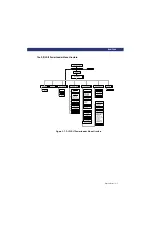
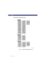
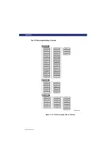
The DLT/SDLT PowerLoader Menu Structure
Figure 3-8. DLT/SDLT PowerLoader Menu Structure
Library Status
Product Type
Firmware Rev
Date
Time
Loader status
Library Mode
Library Config
Vendor ID
Product ID
Transport Addr
Storage Addr
Transfer Addr
Serial Number
Wide SCSI
SCSI Bus ID
SCSI BUS Parity
Negotiation Mode
Transfer Rate
Unload Mode
Auto Clean
Reserved Slots
Mode Page 1f Length
TUR Reporting
Init Elem Status
Unit Attn Report
Boot Version
Flash Type
Baud Rate
Barcode Reader
Label Size
Label Alignment
Abort Move Status
SCSI Mode
Post Rec'vd Error
TApe Alert Mode
Cln Cart Count
DLT/SDLT1
Slot 1 Status
Slot 2 Status
Slot 3 Status
Slot 4 Status
Slot 5 Status
Slot 6 Status
Slot 7 Status
Slot 8 Status
Slot 9 Status
Slot 10 Status
Slot 11 Status
Slot 12 Status
Slot 13 Status
Slot 14 Status
Slot 15 Status
Map Info
Tape Motion
Product Type
Tape Format
Compression
SCSI Bus ID
Drive Rev
Firmware Rev
Cartridge Pres
Hardware Error
Media Error
Write Protected
Serial Number
DLT/SDLT Status
LXM-0004b
Auto Home
DLT/SDLT1
Содержание LXLS10
Страница 1: ......
Страница 4: ...xii u Preface PREFACE...
Страница 8: ...iv TABLE OF CONTENTS CONT D...
Страница 10: ...x LIST OF TABLES CONT D...
Страница 18: ...1 6 u Introduction TAPE CARTRIDGE MAGAZINE...
Страница 86: ...A 4 u Specifications SPECIFICATIONS Declaration of Conformity...
Страница 90: ...Index 2 INDEX...


