13
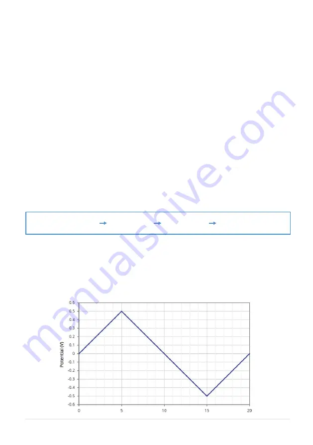
Start Potential Potential Vertex 1 Potential Vertex 2 Start Potential
Figure 9.1.
Example of a cyclic voltammetry scan profile for a start potential of 0 V, potential vertex 1 of 0.5 V,
potential vertex 2 of -0.5 V, and scan rate of 100 mV/s.
9. Operation
1. Add your appropriate electrolyte solution into the electrochemical cell.
2. Place the lid on the cell and insert the working, counter, and reference electrodes.
3. Use the cable and crocodile clips to connect the sockets on the front of the Potentiostat to the
appropriate electrodes.
I. The red clip connects to the working electrode.
II.
The black clip connects to the counter electrode.
III. The blue clip connects to the reference electrode.
4. Start the Ossila Cyclic Voltammetry software. The window shown in
Figure 9.2
will open.
5. Enter the appropriate settings for your experiment into the software (explained in more detail in
Section 9.2
).
6. Click the ‘Measure’ button.
I. The system will sweep the potential between the working electrode and reference electrode,
whilst measuring the current between the working electrode and counter electrode, in the
follow steps:
II. This will be repeated for the specified number of cycles.
7. If ‘Save After Measurement’ is turned on, the measurement data and settings will be saved once the
sweep has completed.
9.1 Taking a Measurement
Содержание T2006A
Страница 25: ......


