CAS40P 40 CFM / 100 PSIG
SECTION 6: MAINTENANCE
PAGE - 33
®
An Oshkosh Corporation Company
as indicated by [
F
] in
Figure 6-1
, and hand-
tighten.
Refer to
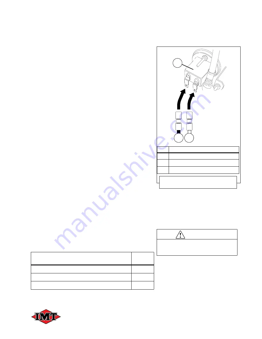
Figure 6-3
for step #3.
3. Reconnect the two (2) designated wires from
the wiring harness to their proper
connections on the two (2) hour meter [
A
]
connections: The designated black wire
connects to the left side; the designated
white wire to the right, as shown in
Figure 6-
3
.
Refer to
Figure 6-2
for step #4.
4. Reconnect the tubing from the elbow on the
pressure gauge assembly (refer to
Figure 6-
2
, items
B
and
B
1
).
Refer to
Figure 6-1
for steps #5 and #6.
5. Loosely replace the remaining sets of 1/4-20
truss screws [
D
] and 1/4” nylon flat washers
[
E
] into the remaining mounting holes of the
instrumentation-side panel.
6. Tighten
all
panel truss screws, in sequence, to
secure.
6.4.2 CHECKING PRESSURE GAUGE
Perform a visual inspection each time the compres-
sor is started to ensure that the pressure gauge is
operating normally. Allow the compressor to warm
up, and verify that the pressure gauge is within its
recommended range. Such inspections will minimize
the possibility of damage or an unsafe condition from
occurring. Refer to
Section 3: Specifications
.
6.4.3 COMPRESSOR SYSTEM LUBRICATION
The compressor is fully charged at the factory with a
synthetic based lubricant. This section gives details
on checking and changing the compressor oil.
The compressor oil level sight glass is accessible
from the outside of the canopy.
System Component Group
Manual
Section
Compressor System Lubrication
6.4.3
Oil Level Check
6.4.3.1
Changing the Compressor Oil
6.4.3.2
KEY
DESCRIPTION
A
HOUR METER RECONNECTION
A
1
BLACK WIRE (Hour Meter Designated)
A
2
WHITE WIRE (Hour Meter Designated)
Figure 6-3: Instrument Panel Wire
Reconnections
A
1
A
2
A
CAUTION
DO NOT mix oil types, weights, or
brands. Mixing oil types can cause
equipment damage or failure.
Manual #99905382 Rev 02
(JUNE 2018)


