4.4.
Installing
To ensure high-quality operation of the detector, the next principals recommended during in-
stallation:
●
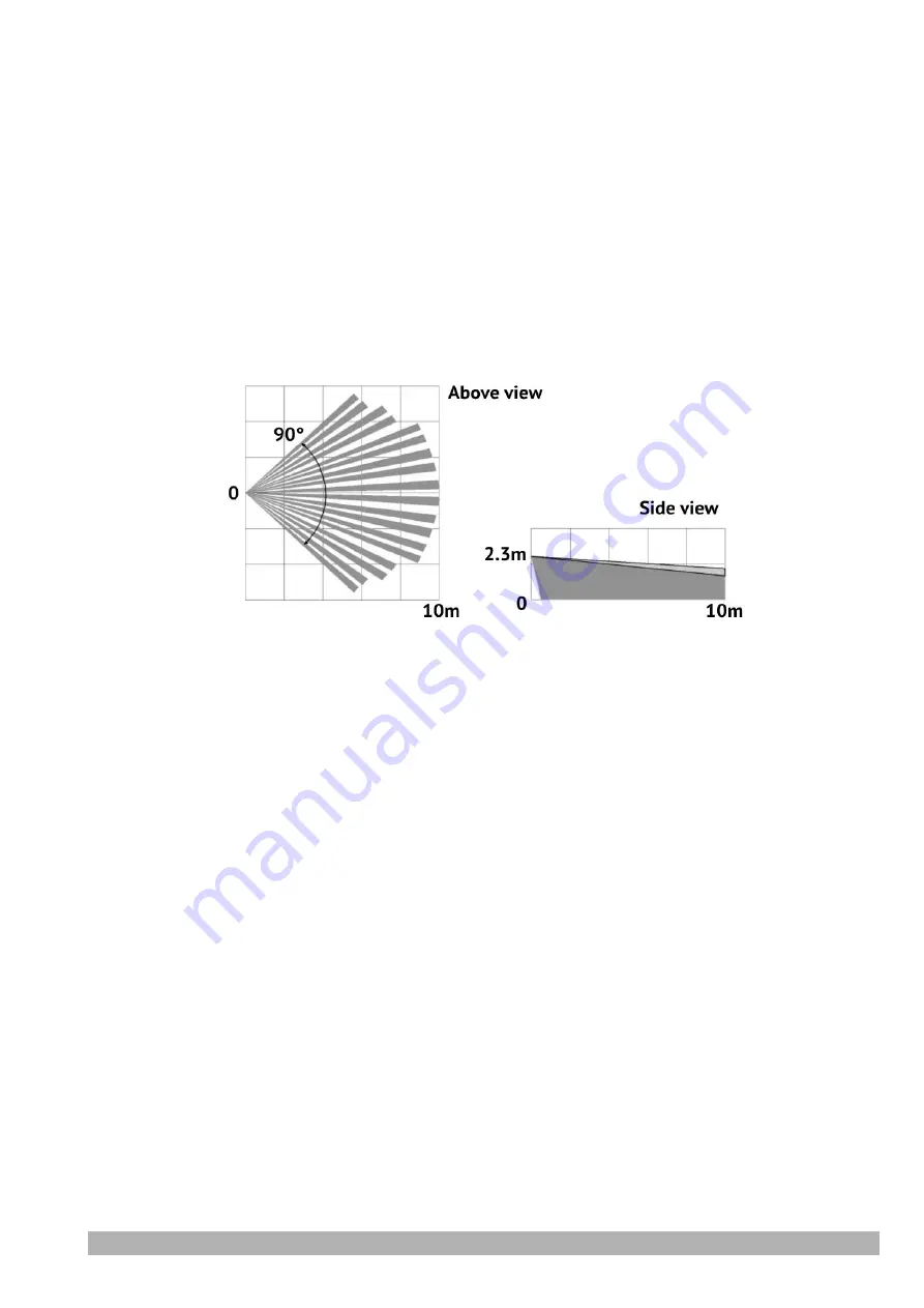
Place the detector at a height of 2.3 m from the floor of the room;
●
Ensure that there are no obstacles (for example, curtains, indoor plants, cabinets, shelv-
ing, glass and mesh partitions) in the detection zone;
●
Avoid getting windows, air conditioners, heaters, radiators, as well as furniture that ani-
mals can climb into the detector detection zone, approaching the detector at a distance
of less than 2m;
●
Ensure that the distance from the detector to electrical cables is at least 0.5m.
To install the detector:
1. Choose a place for installation, taking into account the signal strength in this place (see
section 4.3) and the diagram of the detection zone (Figure 2);
Figure 2. Zone detection diagram
2. Press the lock in the lower part of the housing, then remove the detector cover with the
board and battery;
3. Drill holes in the bottom of the housing for mounting the detector on the wall. To protect
against tearing, use at least one of the places located on the tamper sensor;
4. Mark the places for mounting the detector on the wall according to previously drilled
holes in its housing. Remember that the permissible deviation of the detector from the
vertical is no more than 2º. Drill holes in the wall according to the markup;
5. Fix the bottom of the detector housing in the selected place;
6. Close the detector cover with the circuit board and battery.
5. Maintenance
The product work should be checked annually.
6. Operating conditions
1. Detector is designed for continuous operation.
2. Detector shall be used at the temperature of –20°С to +55°С and relative humidity of 5% to
85%.
3. If the transportation conditions differ from the operating conditions, then the detector must
be kept in the operating conditions for 2…6 hours before switching on.
PIR-R
Version en_2
6


