4
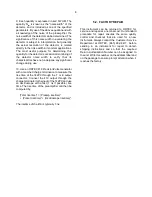
Fig. 4.1. Simplified Block Diagram of the 142PC Preamplifier.
these tests. an SHV tee can be inserted between
the Input connector and the charge terminator, and
this will then accommodate the test capacitances.
Do not furnish any bias during these tests.
3.5. DETECTOR BIAS INPUT
Operating bias for the proportional counter detector
is supplied to the Bias connector on the 142PC and,
through a filter and a large bias resistance, to the
Input signal connector. From there it is furnished
out through the signal input cable to the
proportional counter.
Connect a cable from the detector bias supply
(ORTEC 459 is typical) to the Bias connector on the
142PC. Type SHV connectors are used in this high-
voltage circuit and the mating cable should be
furnished with the bias supply module.
4. OPERATION
4.1. GENERAL
When the 142PC is installed according to the
appropriate information in Section 3, it operates at
all times when power is applied from the power
source; this is either from the bin and power supply
through a mating amplifier or from an ORTEC 114
Preamplifier Power Supply. The only adjustment
that will be made in or on the pre- amplifier is an
internal risetime adjustment that is accessible
through the case of the unit.
Figure 4.1 is a simplified block diagram of the
circuits in the 142PC Preamplifier. When the
protection circuit is in, the diode clamp to ground
from a point between two resistors in the input
circuit will protect the input FET transistor from
large transients, which are not a part of the input
pulse information. When the protection circuit is
out, there is no clamp to ground and the two series
input resistors are shorted by a jumper.
Содержание 142PC
Страница 4: ...iv...
Страница 8: ...viii...


