1
ORTEC MODEL 142PC
PREAMPLIFIER
1. DESCRIPTION
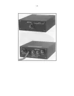
The ORTEC 142PC Preamplifier is a charge-
sensitive unit that is designed for use with
proportional counters in applications such as soft x-
rays or low-energy gammas for spectroscopy where
resolution approaching the theoretical limit is
desired. It has been designed to provide the
ultimate in both energy and timing resolution. The
gain provided by the 142PC allows the counter to
be operated at substantially lower voltages, thus
reducing peak position shifts and peak broadening
due to space charge effects in the tube and
simultaneously extending the tube life.
A bias circuit is included to accept the operating
voltage that is required. for the proportional counter.
The bias circuit in the preamplifier includes about
29.5 megohms of resistance, and any detector
leakage current will have to pass through this high
resistance. A voltage drop is expected across this
load resistance, proportional to the detector leakage
current, and this must be added to the bias value to
determine the adjustment level for the bias supply.
An input protection circuit is built into the
preamplifier. It protects the input FET from any
large transient voltages that would otherwise
damage the transistor. This is discussed in the
Notice (inside front cover). The protection circuit
also provides a damping resistance on the input so
that relatively long cable lengths can be used
between the proportional counter and the
preamplifier without disrupting the system stability.
An internal risetime compensation adjustment is
accessible through a hole in the case of the unit.
See Section 4.5 for adjustment information.
A Test Pulse connector with a built-in charge
terminator is provided for use with a pulse
generator such as the ORTEC 419, 448, or 480 to
simulate the signal from the proportional counter.
This allows a check of the system performance
while an experiment is in progress.
The 142PC will accommodate up to ±3000 V bias
for the proportional counter. The output pulse
polarity is the same as the applied bias polarity. The
142PC Preamplifier output can be connected to a
shaping main amplifier such as the ORTEC 451,
485, or 572 for energy spectroscopy, or to a timing
filter amplifier such as the ORTEC 474 for time
spectroscopy.
If it is necessary to open the case for any reason,
observe the following instructions carefully to
prevent serious injury to yourself and/or damage to
the instrument.
Observe the steps that are included in the Notice at
the front of the manual to discharge the high
voltage and prevent shock: the voltage levels that
can be used are lethal and the capacitors are very
high quality so they retain a charge much longer
than normally expected.
Do not touch the high-megohm resistors. R4 and
R7, with your bare fingers; the presence of skin oil
can reduce the resistance of the component and
alter operating characteristics.
See Section 4 for instructions that involve the
protection circuit.
Содержание 142PC
Страница 4: ...iv...
Страница 8: ...viii...


