7
normal capacity of the detector and associated
cables should be replaced by a capacity of equal
value placed across the input connector, and no
bias should be applied. This is necessary because
the noise contribution of the preamplifier is
dependent upon input capacity. The only
meaningful statement of the noise level is one that
relates to the spread caused by the noise in actual
spectra. This can be measured and expressed in
terms of the full width at half maximum (FWHM) of
a monoenergetic signal after passing through the
preamplifier and main amplifier system.
The noise performance referenced in Section 2 is
stated in these terms, and verification methods will
be described. If desired, the preamplifier can be
tested with no external capacity on the
Input connector, in which case the noise width
should be approximately that shown for zero
external capacity. In any case, the input connector
and capacitors, when used, should be completely
shielded electrically. A wrapping of aluminum foil
around the Input connector or a shielding cap
attached to the connector will suffice for testing at
zero capacity.
4. The preamplifier must be tested in conjunction
with an associated main amplifier that provides the
required pulse shaping. The typical noise
performance given in Section 2 is obtained using an
ORTEC 572 Spectroscopy Amplifier on which 2-
:
s
time constants have been selected as specified. For
comparison of these tabulated values, it is
preferable to test the preamplifier under identical
pulse-shaping conditions. It is also important to
ensure that the noise level of the input stage of the
associated main amplifier does not contribute
materially to the total noise. This is usually no
problem provided that input attenuators, if any, on
the main amplifier are set for minimum attenuation.
5. If a multichannel analyzer is used following the
main amplifier, testing of the noise performance
can be accomplished by merely using a calibrated
test pulse generator with charge terminator. With
only the charge terminator connected to the the
142PC Input, the spread of the pulser peak thus
analyzed will be due only to the noise contribution
of the preamplifier and main amplifier. The analyzer
can be calibrated in terms of keV per channel by
observing two different pulser peaks of known
energy, and the FWHM of a peak can be computed
directly from the analyzer readout.
6. It is also possible to determine the noise
performance of the preamplifier by the use of a
wide-bandwidth rms ac voltmeter such as the
Hewlett-Packard 3400A, reading the main amplifier
output noise level and correlating with the expected
pulse amplitudes per keV of input signal under the
same conditions. Again, a calibrated test pulse
generator is required for an accurate measurement.
In this method the preamplifier and main amplifier
are set up as they would be used normally, but with
a dummy capacitor (or no capacity) on the Input
connector of the 142PC, and with the ac voltmeter
connected to the main amplifier output. The noise
voltage indicated on the meter, designated E
rms
, is
read and noted. Then a test pulse of known energy,
E
in
(in keV), is applied to the Input and the
amplitude of the resulting output pulse, E
out
is
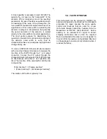
measured in volts with an oscilloscope. The noise
spread can then be calculated from the formula
where E
rms
is output noise in volts on the 3400A
meter, E
in
is input signal in keV particle energy, and
E
out
is output signal in volts corresponding to the
above input. If the gain of the shaping amplifier is
adjusted so that the output pulse height is 2.35 V for
an input of 1 MeV equivalent charge, then the rms
meter will be calibrated directly in energy (1 mV =
1 keV).
7. The noise performance of the preamplifier, as
measured by these methods, should not differ
significantly from that given in the specifications in
Section 2.
8. lf, during testing of the preamplifier and detector,
the noise performance of the preamplifier has been
verified as outlined in the preceding section or is
otherwise not suspected, a detector may be tested
to some extent by duplicating the noise
performance tests with the detector connected in
place and with normal operating bias applied. The
resulting combined noise measurement, made
either with an analyzer or by the voltmeter method,
indicates the sum in quadrature of the separate
noise sources of the amplifier and the detector. In
other words, the total noise is given by
(N
tot
)
2
= (N
det
)
2
+ (N
amp
)
2
.
Содержание 142PC
Страница 4: ...iv...
Страница 8: ...viii...


